LiquidSpring’s ‘Smart Suspension’ Solution
[maghub_sidebar]
Suspended Animation
LiquidSpring’s ‘Smart Suspension’ Solution
Cover
By Bob Livingston
I

f you’ve been paying attention, you’ve noticed that virtually all the suspension enhancements covered in this “Suspended Animation” section have dealt with improving handling and driving comfort derived from leaf-spring underpinnings. Well, they aren’t used exclusively for travel trailers and fifth wheels. For decades, a wide variety of add-on devices have been marketed to improve the ride and road manners of the leaf-spring suspension for the Ford F-53 motorhome chassis, the mainstay of the Class A gasoline-powered motorized industry.

But while many of the add-ons developed by various companies in the aftermarket have tempered the Ford’s road manners to a certain extent, the Ford chassis continues to be known for its stiff ride and, at times, less-than-stellar handling. That’s why Lafayette, Indiana-based LiquidSpring opted to go in another direction. Rather than attempt to “fix” the Ford’s shortcomings by bolting parts to the otherwise stock suspension, LiquidSpring designed a computer-controlled compressible-liquid “smart” suspension system that is installed in place of the Ford chassis’ steel leaf springs and shock absorbers. The system is available for F-53 chassis with 16,000- through 26,000-pound gross vehicle weight ratings (GVWR), dating back to 2011. (Applications for other vehicles also are available.)

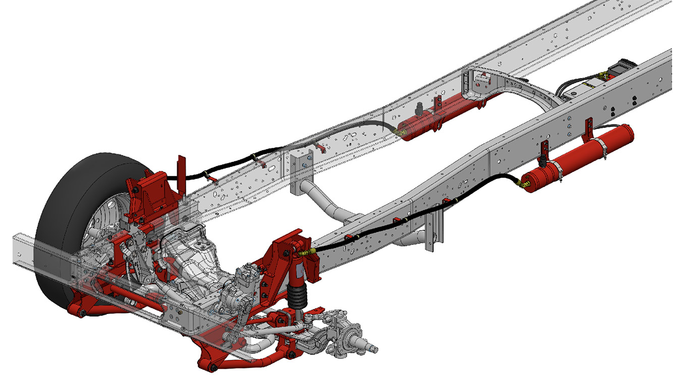
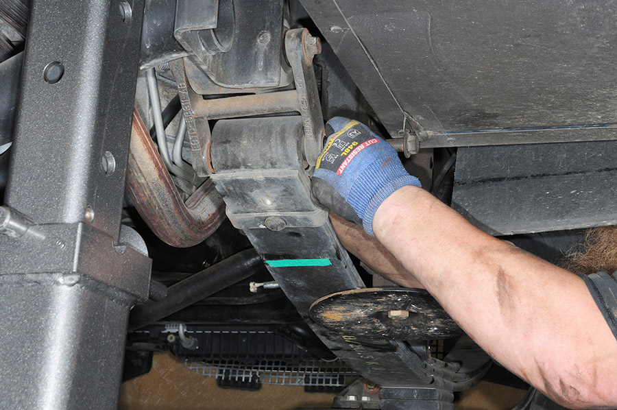
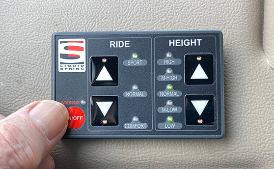
The “liquid” in the LiquidSpring system is silicone-based and compressible under high pressure. Struts (a piston in a cylinder) replace the steel leaf springs. Instead of leaf springs flexing and loading under varying road conditions, the silicone-based liquid is compressed at a variable rate determined by an onboard computer that analyzes suspension movement in milliseconds and changes pressures (2,200 to 4,000 psi) in the struts as road conditions vary. The liquid serves as load support as well as shock absorbing; hence the variability the system provides is a radical transformation of the stock F-53 suspension system. We followed along as the system was installed on the pictured 2016 30-foot Winnebago Itasca Sunstar with an 18,000-pound GVWR chassis.

typical placement of the LiquidSpring
This illustration demonstrates typical placement of the LiquidSpring components on the rear of a Ford F-53 chassis. Factory springs, shocks and hardware are removed and custom brackets for mounting controls arms and struts are mounted to the frame. A control module (partially hidden) and volumes (tanks) manage the flow of liquid to the struts. Limited frame real estate in the test motorhome required the volumes be moved behind the rear axle.
Removed from the chassis were the four stock leaf spring assemblies and shock absorbers, plus their mounts and hardware — all replaced by LiquidSpring equipment. Among the components built at the Lafayette plant are the struts and pressurized tanks (which the company calls “volumes”), plus the control module/liquid reservoir, mounting brackets and other hardware.

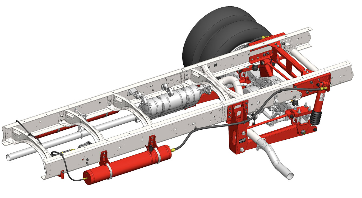
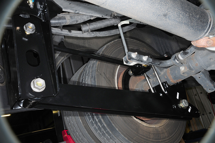
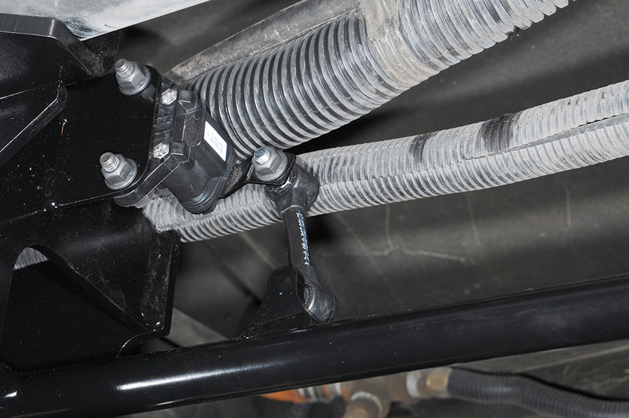
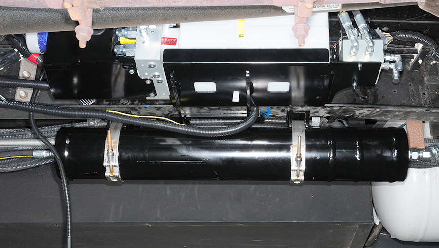
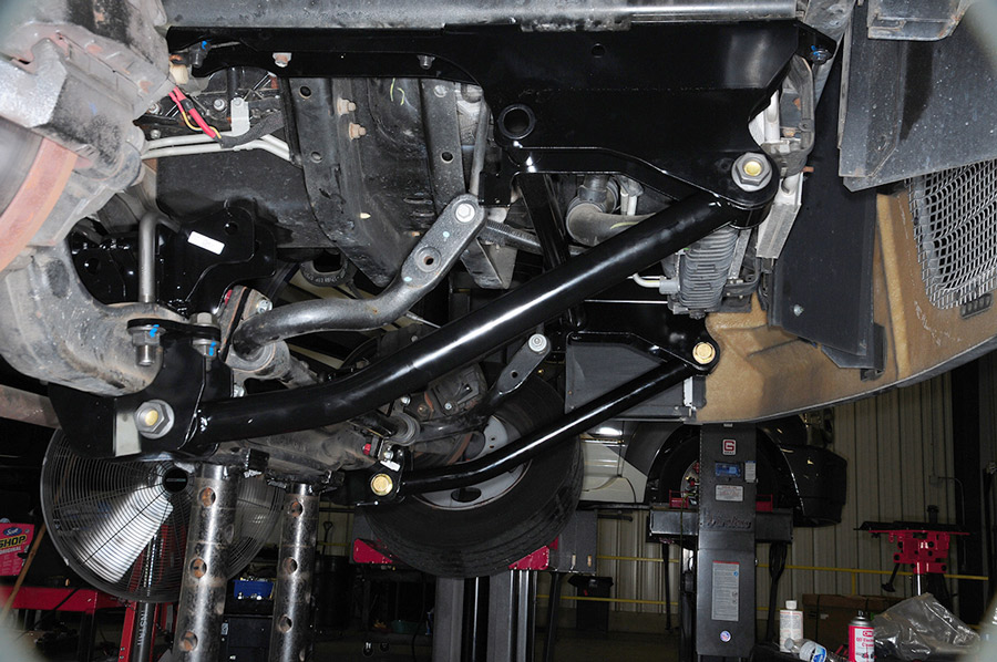
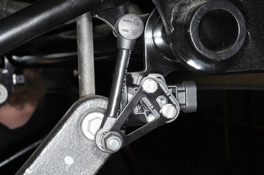
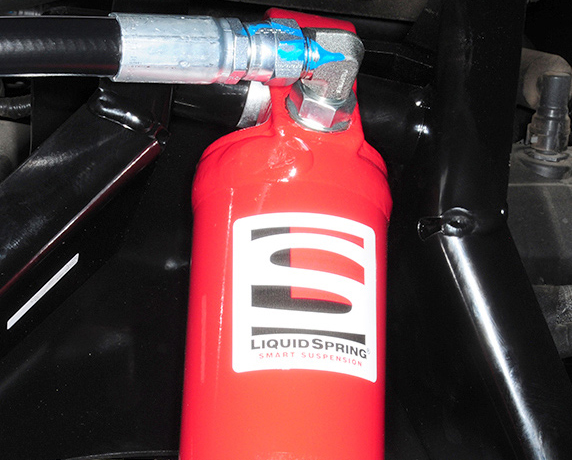
As noted earlier, the actual “spring” in the LiquidSpring system is a strut consisting of a tube and piston. Each wheel strut is connected by a high-pressure hose to a volume, and the pressure in that volume is controlled via another high-pressure hose to the control module. The 12-volt-DC-powered module includes a high-pressure pump, computer-controlled valves and a reservoir for the compressible liquid. Pressure in each strut is controlled individually and instantaneously by the module based on data from height sensors at each wheel and a steering sensor. It adds up to an all-wheel variable/adaptive suspension.

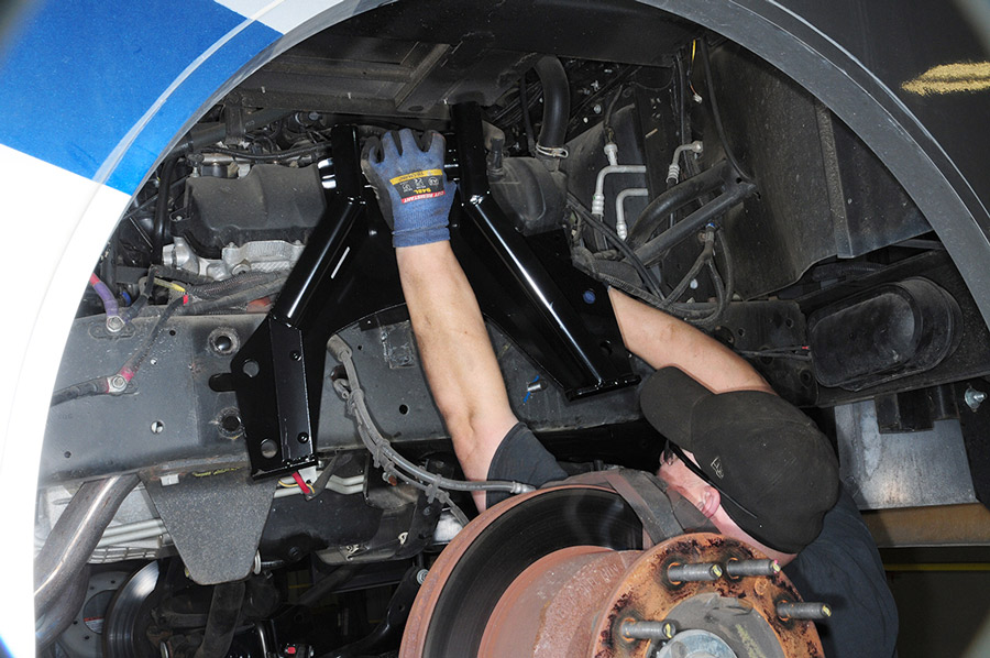
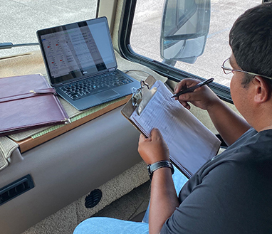
Granted, the LiquidSpring’s suspension did contribute a net increase of 450 pounds to the motorhome, but it was still well within parameters. Curb weight went from 17,160 pounds, loaded (water/fuel propane full, supplies aboard) prior to the LiquidSpring installation to 17,610 due mainly to the weight of the four volumes, the struts and four very substantial control arms front and rear. Ford’s gross axle weight ratings (gawr) for this motorhome were 7,000 pounds front and 12,000 rear; gvwr was 18,000 pounds. Motorhome owners who are considering this installation should acquire accurate weight figures, possibly on one of the many CAT scales at truck stops, because LiquidSpring may decline the installation on a motorhome that already exceeds one or more of its weight ratings.

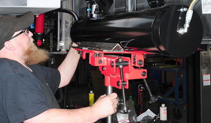
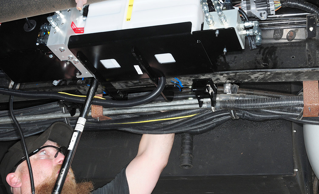
This is neither a quick nor inexpensive transformation. This installation spanned four days at the service department at the LiquidSpring factory in Lafayette and involved the use of four-corner lifts to provide access underneath the Ford chassis. Total parts and labor price for the LiquidSpring smart suspension conversion of the Winnebago Sunstar was $20,000. While this price is obviously more than you’ll pay for one of the many other F-53 upgrades available, the investment may not seem as daunting once the full scope of benefits are realized.

The owner reported back that ride was dramatically smoother and controlled even on broken pavement riddled with repairs and potholes. The LiquidSpring system substantially reduced the repeated shock impulses transmitted by the stock leaf springs on rough pavement, and it muted the noise. On curves, the motorhomes did not heel over and yaw, even during aggressive maneuvering. It stayed mostly flat on the pavement; a winding road became a pleasurable drive. Rough approaches to highway bridges were no longer feared. Rapid lane changes produced very little body roll and yawing effect.

Essentially, the LiquidSpring system transformed the Ford F-53 suspension into something more akin to an air-suspension system on a diesel-pusher coach — and, let’s face it, ride quality is oftentimes one of the reasons buyers opt for more expensive rear-diesel coaches.

front suspension for the Ford F-53 chassis
The front suspension for the Ford F-53 chassis is the latest offering from LiquidSpring. Like the installation process for the rear, the springs, shocks and hardware are removed to make way for brackets, control arms and struts. Volumes were mounted on the frame midship; a single control module, configured for both the front and rear, was mounted close to the volumes on the test motorhome.
magnetic frame drill
installing suspension
A magnetic frame drill is an indispensable tool for installers, who will have to create new holes for the LiquidSpring fasteners. Installation began at the rear, where new suspension brackets were dry fit first, then bolted to the frame. Hanger-crossmember is bolted to the frame above the rear axle housing. Additional brackets will be added to this hanger later in the installation.
attaching lower control arm
Brackets to accept control arms and strut
With new brackets for the upper and lower control arms bolted to the frame and torqued to specifications, a new lower control arm is attached to the front bracket that’s attached to the frame and swung into the rear bracket where it will be bolted in place. Brackets to accept control arms and strut are attached to the rear axle using U-bolts and new upper and lower controls arms are bolted between the axle and frame. These components take the place of the original leaf springs.
rear strut
The rear strut is bolted in place between the upper frame and lower axle brackets. The strut plays a pivotal role in controlling the suspension. New jounce bumpers are attached to the frame on proprietary plates to replace those provided from Ford.
height sensor is connected via ball studs
The height sensor is connected via ball studs to the upper control arm on both sides. Information from this sensor will supply important information to the system control module.
control module
installing fittings in the connection ports
The control module (also called the Isolation manifold and fluid reservoir) is prepared on the bench before final installation in brackets that have been attached to the frame. It takes some study to find the right place to install this component, which must have adequate clearance from the exhaust system. Fittings are installed in the connection ports while the control module is still on the bench. These fittings will accept the hoses that distribute fluid to the struts and volumes. The entire unit fits securely into the space along the frame and provides just enough clearance to reach the reservoir fill — something that is not needed very often once the installation is complete. Only one control manual is needed for both the front and rear suspension.
volume for front suspension
One of the volumes for the front suspension is installed in a logical place near the control module. Again, it takes some study to find the right places to install the volumes, which are attached via special brackets and robust steel bands.
stripping leaf springs, shocks and factory hardware
axle clamp group components
Leaf springs, shocks and factory hardware are stripped from the frame up front to get ready for installing the LiquidSpring components. The front project starts with the installation of the axle clamp group components. Factory Huck bolts are removed using a grinder to make way for frame-stiffening plates and component brackets. Here, the upper controls arms have been bolted in place.
positioning upper strut/crossmember mount
The upper strut/crossmember mount is carefully put into position and bolted to the upper bracket and lower control arm. The struts are the heart of the new suspension system.
height sensors
Front height sensors are installed on the upper controls arms to corresponding positions on the frame brackets. Height is measures at all four corners of the LiquidSpring suspension. The steering sensor is also installed on the Pitman arm and new jounce bumpers are bolted to plates on both sides of the front frame.
hydraulic hoses connected to the struts
Extensive wiring harnesses were routed to the control module, height and steering sensors and to the cockpit and hydraulic hoses are connected to the struts, control module and volumes. Any hose that passes through an area that may cause abrasion is wrapped with a protective conduit.
Large rear volumes
Rear volumes (the larger ones) were mounted behind the rear axle because the motorhome chassis was on the short side and did not provide enough room closer to the front. Hoses are then attached and secured, with heat-resistant conduit placed around any hydraulic hose that was near the exhaust and/or passing through areas where sharp edges might exist.
dash-mounted control panel
A dash-mounted control panel allows the driver to set ride parameters to Sport, Normal and Comfort. It also controls ride height. The panel also includes a five-choice Height setting. At speeds below 15 mph, this is helpful; dial it High if there is any chance of dragging the rear of the motorhome while entering a driveway or dial it Low after parking at a campsite so the motorhome’s jacks have less of a lifting job and the entry step will be lower. The difference (lift) between the two settings is about 5 to 6 inches, depending on terrain.
technician installing control module
After completing the install under the motorhome and installing the control module on the dash, a technician will connect a computer to program the system. Programming is started in the shop and continued during a test run on the road.