Rx for Ride and Handling
[maghub_sidebar]
Rx for Ride and Handling
The Itasca motorhome is placed on a four-corner, electric lift and supported by tall jack stands to release the suspension
The Itasca motorhome is placed on a four-corner, electric lift and supported by tall jack stands to release the suspension. Installation was completed in the LiquidSpring facility in Lafayette, Indiana.
LiquidSpring’s ‘smart suspension’ solution to the inherent harsh ride of the Ford F-53 motorhome chassis
By Bob Livingston / Photos by the author
F

or decades, a wide variety of add-on devices have been marketed to improve the ride and road manners of the leaf-spring suspension for the Ford F-53 motorhome chassis, which has been the mainstay of the Class A gasoline-powered motorized industry. While many of the add-ons developed by various companies in the aftermarket have tempered the Ford’s road manners to a certain extent, the Ford chassis continues to be known for its stiff ride — and, at times, less-than-stellar handling.

Lafayette, Indiana-based LiquidSpring opted to go in another direction. Rather than attempt to “fix” the Ford’s shortcomings by bolting parts to the otherwise stock suspension, LiquidSpring designed a computer-controlled compressible-liquid “smart” suspension system that is installed in place of the Ford chassis’ steel leaf springs and shock absorbers. The system is available for F-53 chassis with 16,000- through 26,000-pound gross vehicle weight ratings (GVWR), dating back to 2011.

The “liquid” in the LiquidSpring system is silicone-based and compressible under high pressure. Struts (a piston in a cylinder) replace the steel leaf springs. Instead of leaf springs flexing and loading under varying road conditions, the silicone-based liquid is compressed at a variable rate determined by an onboard computer that analyzes suspension movement in milliseconds and changes pressures (2,200 to 4,000 psi) in the struts as road conditions vary. The liquid serves as load support as well as shock absorbing; hence the variability the system provides is a radical transformation of the stock F-53 suspension system.

illustration demonstrates typical placement of the LiquidSpring components on the rear of a Ford F-53 chassis
This illustration demonstrates typical placement of the LiquidSpring components on the rear of a Ford F-53 chassis. Factory springs, shocks and hardware are removed and custom brackets for mounting controls arms and struts are mounted to the frame. A control module (partially hidden) and volumes (tanks) manage the flow of liquid to the struts. Limited frame real estate in the test motorhome required the volumes be moved behind the rear axle.
front suspension for the Ford F-53 chassis
The front suspension for the Ford F-53 chassis is the latest offering from LiquidSpring. Like the installation process for the rear, the springs, shocks and hardware are removed to make way for brackets, control arms and struts. Volumes were mounted on the frame midship; a single control module, configured for both the front and rear, was mounted close to the volumes on the test motorhome.
LiquidSpring got its start a couple of decades ago in mining equipment (see sidebar) and has been led for several years by President and CEO Dean Bartolone, a professional engineer who emphasizes quality, sophisticated design elements and manufacturing. Most components are designed and built in-house. Swedish steel made from ore is used for the components, rather than steel made at least in part from recycled sources such as discarded engine blocks. By controlling the physical properties and quality of the steel used, the LiquidSpring components are actually harder than the steel formed for the chassis, said Bartolone, which ensures durability in a hostile road environment. In-house design and manufacturing also permit rapid design modifications and testing as needed.

Beyond the Ford F-53, suspension conversions also are available for Ford-based ambulances and other Ford trucks, plus Ram 5500 and specific International Durastar and Freightliner chassis, buses and work trucks. LiquidSpring products are available through a network of authorized dealers/installers in the U.S. and Canada.

For our test, the LiquidSpring system was fitted on a 2016 30-foot Winnebago Itasca Sunstar (similar to Winnebago’s Vista) with an 18,000-pound GVWR chassis. LiquidSpring initially released only a system for the rear in this application, which did a commendable job of controlling body roll and bounciness. For this installation the front conversion was also made, which dramatically changes the paradigm when it comes to handling improvement and overall comfort while driving the motorhome over rough roadways. We drove almost 5,000 miles (combined, before and after) on a variety of Interstate highways and local roads across six states to road-test this suspension, part of which was a controlled 39-mile course for repeatability.
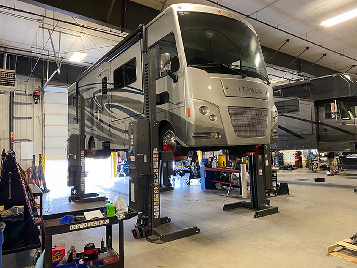
The Installation
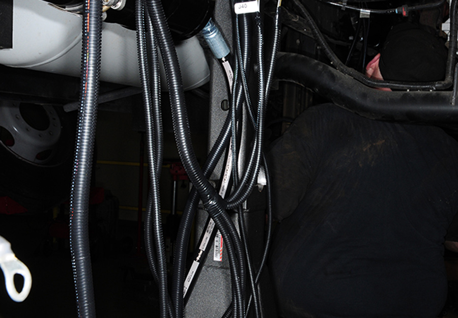
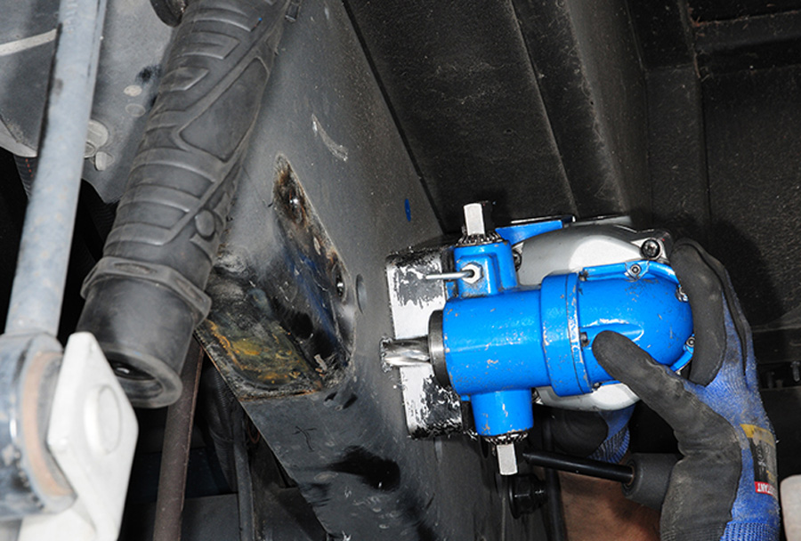
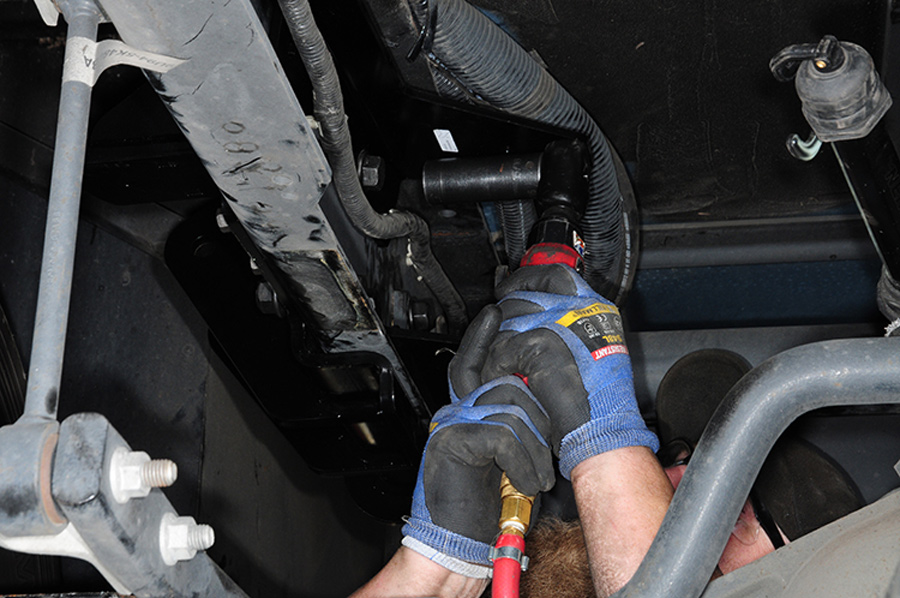
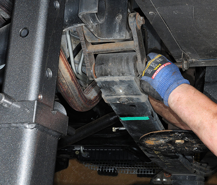
Our test installation, performed in the service department at the LiquidSpring factory in Lafayette, took four days and involved the use of four-corner lifts to provide access underneath the Ford chassis. Removed from the chassis were the four stock leaf spring assemblies and shock absorbers, plus their mounts and hardware — all replaced by LiquidSpring equipment. Among the components built at the Lafayette plant are the struts and pressurized tanks (which the company calls “volumes”), plus the control module/liquid reservoir, mounting brackets and other hardware.

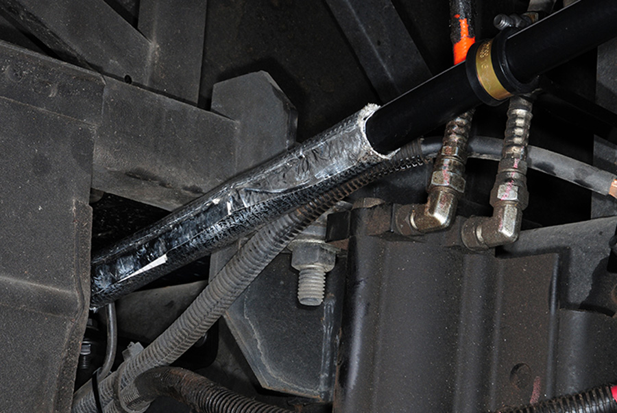
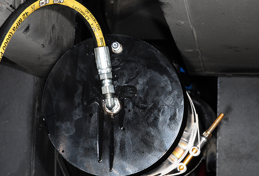
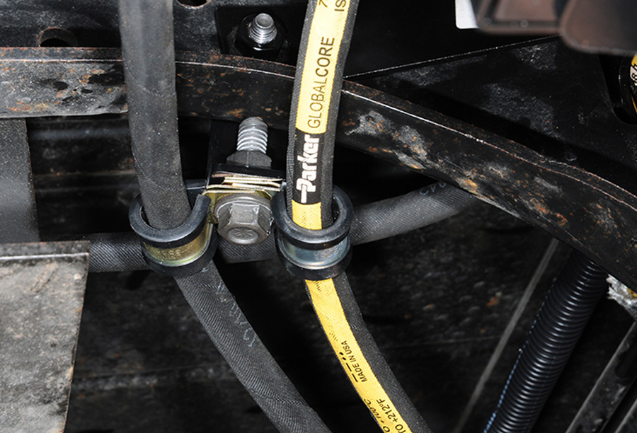
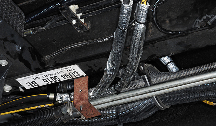
As noted earlier, the actual “spring” in the LiquidSpring system is a strut consisting of a tube and piston. Each wheel strut is connected by a high-pressure hose to a volume, and the pressure in that volume is controlled via another high-pressure hose to the control module.

weighing each corner of the motorhome using wheel scales
Before starting the tear down, the technician weighed each corner of the motorhome using wheel scales. If there is an overweight condition, the LiquidSpring system will not be installed. Weight determinations were repeated after the project was completed.
install started with the rear suspension
Once the motorhome was situated securely on the four-corner lift with tall jack stands in place, the install started with the rear suspension. Leaf springs, shocks and all stock brackets were removed and placed on a wood pallet.
The 12-volt-DC-powered module includes a high-pressure pump, computer-controlled valves and a reservoir for the compressible liquid. Pressure in each strut is controlled individually and instantaneously by the module based on data from height sensors at each wheel and a steering sensor. It adds up to an all-wheel variable/adaptive suspension.

In our installation, the larger volumes are 6.5 by 38.5 inches, attached by hoses to the rear struts and placed behind the rear axle. On longer chassis the volumes usually are mounted between the axles, which will likely present fewer challenges in locating the appropriate brackets. Volumes for the front struts are 4.75 x 30.75 inches. The size of the volumes may vary in applications for higher-rated chassis.

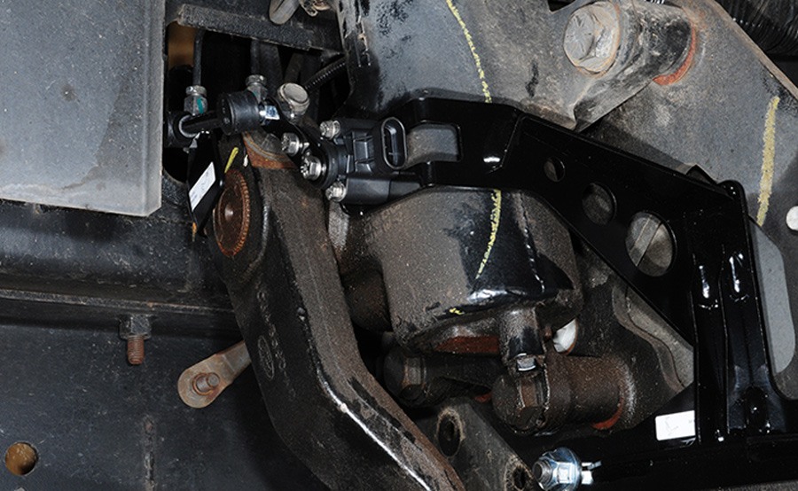
The process was handled competently and carefully by a company technician who meticulously routed and secured all the components and hoses. Although the front suspension was replaced, the steering components were not altered. Nevertheless, the steering wheel was slightly off-center when the project was completed, a direct result of raising the ride height with the addition of the LiquidSpring suspension components. This is usually an easy fix, requiring the removal and repositioning of the steering wheel; instructions are provided to make any corrections. LiquidSpring technicians normally take care of this during the installation process, but we ran out of time on a Friday, and headed down the road before making the correction.

A Few Words on Tires
The weight increase of the LiquidSpring package (450 pounds) did not justify higher tire pressure than what we were carrying — 80 psi in all tires — and the tires were loaded below their maximum load ratings, which were 7,280 front axle (two tires) and 13,660 rear axle (four tires).

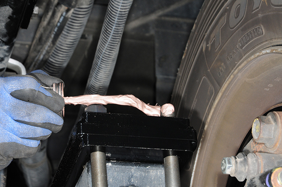
Choice of tires apparently can adversely affect ride quality in the 190-inch-wheelbase 18,000-pound-rated Ford F-53 chassis — possibly more so than in higher-rated chassis with 22.5-inch tires. Stock tire size is 245/70R19.5 and the chassis originally was fitted by Ford with Goodyear G670 tires in load range G, which are known to be comparatively soft-riding tires for motorhome service. The motorhome owner had replaced those with Toyo M154 tires in the same size but in load range H; they had stiffer sidewalls and were over-rated for the weight of the motorhome.

Sales literature for most tire brands in the 19.5-inch size emphasize urban delivery-truck service, not soft ride in a motorhome (except for the Goodyear G670 and Michelin XRV).

magnetic frame drill
A magnetic frame drill is an indispensable tool for installers, who will have to create new holes for the LiquidSpring fasteners. This tool is listed as a mandatory item in the installation instructions.
The result was an even harsher ride than stock prior to the LiquidSpring installation — adding to the already existing ride stiffness problem with the Ford chassis. But the LiquidSpring system improved ride comfort despite more tire stiffness than the stock chassis may have had. Owners with stock tires will likely see an even greater improvement in ride quality.

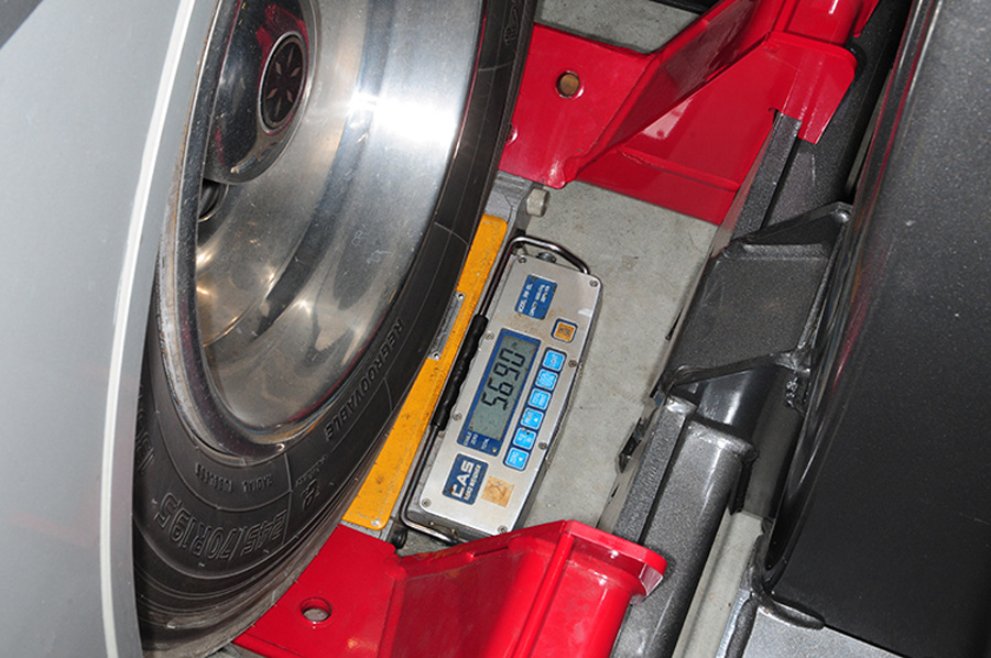
The motorhome weighed 17,160 pounds, loaded (water/fuel propane full, supplies aboard) prior to the LiquidSpring installation. Afterward, weight increased to 17,610 due mainly to the weight of the four volumes, the struts and four very substantial control arms front and rear.

Ford’s gross axle weight ratings (GAWR) were 7,000 pounds front and 12,000 rear. Other Ford chassis with longer wheelbases are rated up to 26,000 pounds. Motorhome owners who are considering this installation should acquire accurate weight figures, possibly on one of the many CAT scales at truck stops, because LiquidSpring may decline the installation on a motorhome that already exceeds one or more of its weight ratings.

Road-Testing the Results
“Dramatically quieter. Amazing.” We used those words in describing the level of improved ride and handling of the motorhome after the LiquidSpring installation versus a similar — and extensive — nearly 2,500-mile trip across the same type terrain following the installation.

As an example, ride was dramatically smoother and controlled even on broken pavement riddled with repairs and potholes. The truck lanes on some Interstate highways, such as I-40 east of Albuquerque, New Mexico, were the worst with the stock suspension. The LiquidSpring system substantially reduced the repeated shock impulses transmitted by the stock leaf springs on rough pavement, and it muted the noise.

New suspension brackets are dry fit first, then bolted to the frame
New suspension brackets are dry fit first, then bolted to the frame. This is not a project for inexperienced installers, since all the parts are stout and on the heavy side.
Hanger-crossmember is bolted to the frame above the rear axle housing
Hanger-crossmember is bolted to the frame above the rear axle housing. It might be necessary to weld this component in place, depending on the year and model of the chassis. Additional brackets will be added to this hanger later in the installation.
Motorhomes also tend to rattle as everything from noisy slideouts, kitchen utensils, stove-top grates and assorted supplies and hardware moves around during travel. Although the rattles continued, they were much less offensive. Interestingly, the slide outs in this motorhome were installed with too much tolerance between the openings in the walls the slide structures, which presented some pretty obnoxious squeaking and snarling when driving over bumpy roads. The slides were adjusted by Winnebago during a side trip to Forest City, Iowa, which made a slight difference, but they quieted down substantially after the LiquidSpring components were installed — another testament to the benefits of the system.

On curves, the motorhomes did not heel over and yaw, even during aggressive maneuvering. It stayed mostly flat on the pavement; a winding road became a pleasurable drive. Rough approaches to highway bridges were no longer feared. Rapid lane changes produced very little body roll and yawing effect.

“Perceived ride comfort” is the descriptive phrase for the effect of LiquidSpring, according to Bartolone. It is the combination of better ride quality and road manners with less chassis noises, without the annoying cacophony inside the motorhome that translates to less fatigue and more enjoyable travel.

Essentially, the LiquidSpring system transformed the Ford F-53 suspension into something more akin to an air-suspension system on a diesel-pusher coach — and, let’s face it, ride quality is oftentimes one of the reasons buyers opt for more expensive rear-diesel coaches.

Granted, the LiquidSpring smart suspension is definitely not a project for the do-it-yourselfer. However, in addition to its factory installation center, LiquidSpring is associated with a number of independent suspension repair/modification shops in various locations that are available on the company website. Motorhome manufacturers also can order the bare chassis from Ford with the LiquidSpring suspension components already installed; Tiffin Motorhomes and Fleetwood RV, for example, offer the LiquidSpring suspension as an option from the factory.

Brackets for the upper and lower control arms are bolted to the frame and torqued to specifications
Every bolt in this system is final tightened with a torque wrench
Brackets for the upper and lower control arms are bolted to the frame and torqued to specifications. Every bolt in this system is final tightened with a torque wrench. Once the bolt is torqued to specification, it is painted to correspond with the frame to indicate that it has been tightened properly and to let other mechanics know that the bolt requires torquing if removed for some reason down the road.
Total parts and labor price for the LiquidSpring smart suspension conversion of our test Winnebago Sunstar was $20,000. While this price is obviously more than you’ll pay for one of the many other F-53 upgrades available, the investment may not seem as daunting once the full scope of benefits are realized. It’s not uncommon for owners of higher-end gas-powered motorhomes that meet their lifestyle needs to trade for a diesel pusher simply to circumvent dissatisfaction with the poor ride quality and handling manners of the Ford F-53 chassis.

In most cases, selling or trading a perfectly good gasser results in a big depreciation hit — and when combined with the depreciation of the new motorhome, the financial loss can be substantial. Investing $20,000 in a motorhome in excellent condition that will easily rival the ride quality of a diesel pusher may be the more cost-effective option. Again, there are other factors to consider, including an owner’s level of satisfaction with his or her current gas motorhome and travel patterns, but the numbers will generally favor making the LiquidSpring transformation.

The LiquidSpring system is the first real fix for the historically stiff ride of the Ford F-53 motorhome chassis, and it does an excellent job of improving handling and road manners while reducing interior noise. Combine these benefits with far superior suspension components than the factory counterparts, and the expected improved longevity may be the deciding factor for owners tired of enduring a harsh and fatiguing ride.

Lower control arm is attached to the front bracket
Lower control arm is attached to the front bracket that’s attached to the frame and swung into the rear bracket where it will be bolted in place.
Brackets to accept control arms and strut are attached to the rear axle using U-bolts
coating of anti-seize compound is applied to the U-bolt threads before tightening the bolts
Brackets to accept control arms and strut are attached to the rear axle using U-bolts. A coating of anti-seize compound is applied to the U-bolt threads before tightening the bolts to the proper torque specification.
Huge Grade 8
Huge Grade 8 bolts are used throughout the system, requiring strong hands and arms to position into the brackets. This is not a job for the faint of heart.
Upper and lower controls arms
Upper and lower controls arms are bolted between the axle and frame. These components take the place of the original leaf springs.
rear brake line on the right side was replaced with a rubber hose counterpart
line was bled once all the new components were installed
The rear brake line on the right side was replaced with a rubber hose counterpart. This line was bled once all the new components were installed.
rear strut is bolted in place between the upper frame and lower axle brackets
The rear strut is bolted in place between the upper frame and lower axle brackets. The strut plays a pivotal role in controlling the suspension.
New jounce bumpers are attached to the frame on proprietary plates
New jounce bumpers are attached to the frame on proprietary plates. These jounce bumpers replace those provided from Ford.
height sensor is connected via ball studs to the upper control arm on both sides
The height sensor is connected via ball studs to the upper control arm on both sides. Information from this sensor will supply important signals to the system control module.
Final torquing of the control arms will require pure grunt and the help of a second person
Final torquing of the control arms will require pure grunt and the help of a second person. Here the bolts are tightened to 600 ft.-lb., which requires a stout torque wrench. LiquidSpring certifies the accuracy of its torque wrenches on a regular basis.
Control module
prepared on the bench before final installation in brackets that have been attached to the frame
Control module (also called the isolation manifold and fluid reservoir) is prepared on the bench before final installation in brackets that have been attached to the frame. It takes some study to find the right place to install this component, which must have adequate clearance from the exhaust system. Fittings are installed in the connection ports while the control module is still on the bench. These fittings will accept the hoses that distribute fluid to the struts and volumes.
Dialing in the Control Panel
control panel allows driver to set ride parameters to Sport, Normal and Comfort
A control panel allows driver to set ride parameters to Sport, Normal and Comfort. It also controls ride height. We found Sport to offer the best ride control and comfort, although the computer pretty much sets the levels based on road conditions.
A dash-mounted control panel is provided with the LiquidSpring system, offering settings for ride and height. The ride settings include Sport, Normal and Comfort. We couldn’t tell much difference between Sport and the Comfort settings at highway speeds and the Sport position was more enjoyable, so we just left it there. We were told that the computer-driven system pretty much determines ride and handling parameters on its own during travel, and we don’t disagree.
The panel also includes a five-choice Height setting. At speeds below 15 mph, this is helpful; dial it High if there is any chance of dragging the rear of the motorhome while entering a driveway or dial it Low after parking at a campsite so the motorhome’s jacks have less of a lifting job and the entry step will be lower. The difference (lift) between the two settings is about 5 to 6 inches, depending on terrain.
Wiring connections have been sealed against water and debris from entering the plug/receptacle pins
Wiring connections have been sealed against water and debris from entering the plug/receptacle pins. This is necessary to prevent damage from the hostile conditions at the chassis.
After installing the control module, the bolts are torqued to specification
After installing the control module, the bolts are torqued to specification. The entire unit fits securely into the space along the frame and provides just enough clearance to reach the reservoir fill — something that is not needed very often once the installation is complete. Only one control module is needed for both the front and rear suspension.
One of the volumes for the front suspension is installed in a logical place near the control module
One of the volumes for the front suspension is installed in a logical place near the control module. Again, it takes some study to find the right places to install the volumes, which are attached via special brackets and robust steel bands.
Leaf springs, shocks and factory hardware are stripped from the frame up front to get ready for installing the LiquidSpring components
Leaf springs, shocks and factory hardware are stripped from the frame up front to get ready for installing the LiquidSpring components.
front project starts with the installation of the axle clamp group components, which are bolted in place
The front project starts with the installation of the axle clamp group components, which are bolted in place — again using stout fasteners.
Factory Huck bolts are removed using a grinder
Factory Huck bolts are removed using a grinder to make way for frame-stiffening plates and component brackets.
frame hangers are prefit and then bolted in place
Similar to the process for the rear suspension, frame hangers are prefit and then bolted in place.
upper controls arms have been bolted in place
Here, the upper controls arms have been bolted in place. Tall jack stands are used to support the axle, which seems suspended precariously to the untrained onlooker.
pile of original front suspension components
The pile of original front suspension components nearby is a constant reminder of how much work goes into installing the LiquidSpring system.
upper strut/crossmember mount is carefully put into position
The upper strut/crossmember mount is carefully put into position. It was amazing to watch how precisely these components fit into the front suspension configuration.
strut is bolted to the upper bracket and lower control arm
The strut is bolted to the upper bracket and lower control arm. The struts are the heart of the new suspension system.
Front height sensors are installed on the upper controls arms to corresponding positions on the frame brackets
The steering sensor is also installed on the Pitman arm
Front height sensors are installed on the upper controls arms to corresponding positions on the frame brackets. Height is measured at all four corners of the LiquidSpring suspension. The steering sensor is also installed on the Pitman arm.
The Birth of a New Suspension
Many of the bracket components are welded by a robotic arm to ensure a perfect bead
Many of the bracket components are welded by a robotic arm to ensure a perfect bead. Only experienced, certified welders are employed to ready parts for the robotic arm and assemble other components manually.
LiquidSpring hangs its hat on quality control
LiquidSpring hangs its hat on quality control. All the parts are checked for tolerances and pressure tested under strict lab conditions by expert technicians; electrical components are built and checked in clean rooms to assure quality control.
Handling problems have been part of the automotive scene for more than 100 years. Shock absorbers are almost universally relied on to damp suspension movement and have been around for ages; they are expected to take the brunt dished out by bad roads but can only provide so much control. Meanwhile, air bags (air springs) have been offered for more than 50 years. Air bags will help but are still subject to the same tradeoffs between ride quality and handling.

LiquidSpring ventured into the suspension business while tasked with finding a solution for poor ride quality plaguing huge off-road trucks used in underground mining. Typically, these trucks rode so rough that operators were being fatigued by uncontrolled vehicle shaking, creating more down time and less production. LiquidSpring prototyped a suspension for the mining and similar industries that suggested compressible liquid could smooth out the ride enough to make a dramatic difference. In short order, production for those companies that adopted the system doubled while the system also increased suspension longevity and reduced repair down time.

The unique suspension proved to be a worthy improvement, but there were no electronics available to manage the process. The challenge was to develop software that would communicate with the system so spring rates could be changed in concert with the capacity of the springs. By 2012, the company developed a model to understand the characteristics of fluid via electronics and introduced the product to the bus and ambulance industries, which offered dramatic improvements in ride quality. As a LiquidSpring company representative explained, in many cases, the bumpy ride to the hospital before installing the LiquidSpring system increased the fatigue and shock already experienced by distressed patients, which actually degraded their health beyond the problems requiring the ambulance ride. Today, 90% of these ambulances are equipped with LiquidSpring components. This type of improvement was not attainable by the auto industry, which struggled to change spring rate for years without success.

Bringing the LiquidSpring system to the F-53 and cutaway chassis, company engineers had to figure out how fluid changes. A fluid model was built to allow engineers to study what happens to fluid under different temperatures, pressure and flow rates for vehicle control. In the end the model provided the company with the electronics to work with hydraulics and mechanical components — eliminating tradeoffs between ride quality and handling. This was a major milestone.

This type of suspension action is achieved with the use of suspension sensors to regulate height, braking, speed and steering input via proprietary algorithms that allow the system to react to body roll in milliseconds — something shock absorbers and air springs simply cannot do.

New jounce bumpers are bolted to plates on both sides of the front frame
New jounce bumpers are bolted to plates on both sides of the front frame.
Extensive wiring harnesses were routed to the control module
Extensive wiring harnesses were routed to the control module, height and steering sensors and to the cockpit. This took quite a bit of time to route carefully.
Hydraulic hoses are connected to the struts
Any hose that passes through an area that may cause abrasion is wrapped with a protective conduit
Hydraulic hoses are connected to the struts, control module and volumes. Any hose that passes through an area that may cause abrasion is wrapped with a protective conduit.
Rear volumes (the larger ones) were mounted behind the rear axle
Rear volumes (the larger ones) were mounted behind the rear axle because the motorhome chassis was on the short side and did not provide enough room closer to the front. It took quite a bit of ingenuity — and custom brackets — to get these volumes to fit and provide adequate road clearance.
Hydraulic hose is attached to the fitting in the rear volume and routed to the front
New hoses were assembled to allow for the longer run to the control module
Hydraulic hose is attached to the fitting in the rear volume and routed to the front. New hoses were assembled to allow for the longer run to the control module and were attached securely to the frame to prevent any damage down the road.
Heat-resistant conduit was placed around any hydraulic hose
Heat-resistant conduit was placed around any hydraulic hose that was near the exhaust and/or passing through areas where sharp edges might exist.
technician will connect a computer to program the system
After completing the install under the motorhome and installing the control module on the dash, a technician will connect a computer to program the system. Programming is started in the shop and continued during a test run on the road.
system is connected directly to the battery and wired into a holder with an 80-amp fuse
The system is connected directly to the battery and wired into a holder with an 80-amp fuse.
Source:
LiquidSpring
liquidspring.com
(765) 474-7816
Heat-resistant conduit was placed around any hydraulic hose
Heat-resistant conduit was placed around any hydraulic hose that was near the exhaust and/or passing through areas where sharp edges might exist.
system is connected directly to the battery and wired into a holder with an 80-amp fuse
The system is connected directly to the battery and wired into a holder with an 80-amp fuse.
technician will connect a computer to program the system
After completing the install under the motorhome and installing the control module on the dash, a technician will connect a computer to program the system. Programming is started in the shop and continued during a test run on the road.
Source:
LiquidSpring
liquidspring.com
(765) 474-7816