Keeping Tabs on Your Workhorse
[maghub_sidebar]
"Keeping Tabs on Your Workhorse"
Installing new LCD panel on gauge cluster PCB
Not being able to read the LCD instrumentation overseeing your motorhome’s operation can have dire consequences. Fortunately, Brazel’s RV Performance has a cure for this common ailment.
By Bruce Hampson
D

uring an all-too-brief span during between 1999 and model year 2012, the Workhorse Custom Chassis — the successor to Chevrolet’s P-30/P-32 chassis — proved to be a popular choice for manufacturers and owners of gas-powered Class A motorhomes. Not surprisingly, while the now-Workhorse Group Inc. has turned its attentions to other venues, a large number of motorhomes built on Workhorse underpinnings still travel the highways — although not without the occasional hiccup.

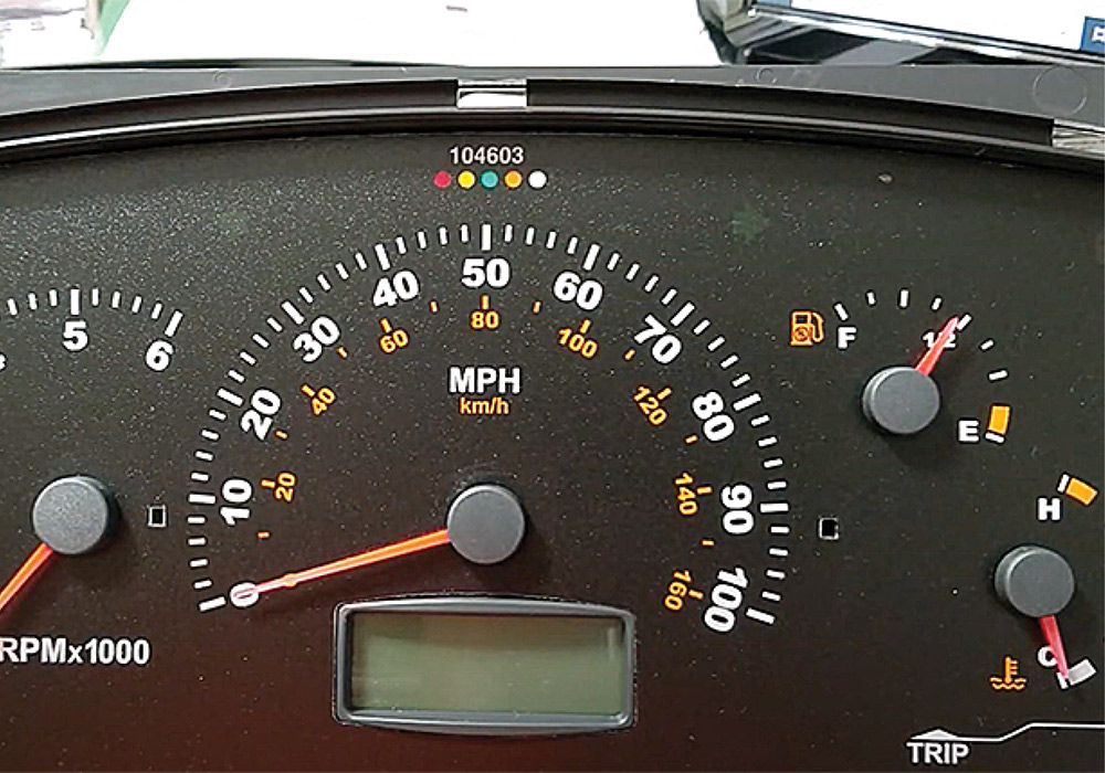
As Jon Brazel pointed out, one component that tends to give Workhorse owners trouble as their vehicles age is the motorhome’s instrument cluster.

“Back when Workhorse was still building motorhome chassis, they would just replace the entire panel,” he said. “The problem was, owners were just getting the same product that would fail again in a few years.”

Original stock LCD in speedometer
New LCD in speedometer
The stock LCD in Caudill’s Winnebago was beginning to pixelate, making it tough to read — especially while driving. Brazel’s replacement screen kit, on the other hand, illuminates against a blue background (which can be adjusted for brightness), making it easy to glance down to see what’s going on.
Brazel, parts manager for Brazel’s RV Performance and its Ultra RV Products parts distribution division, looked into the problem along with company technicians and discovered that the liquid-crystal display (LCD) screens used would eventually delaminate — and the pixels would begin disappearing. That left owners in the lurch, without the ability to monitor everything from the odometer and oil pressure to battery voltage, gear shift position, engine warnings and diagnostic features.

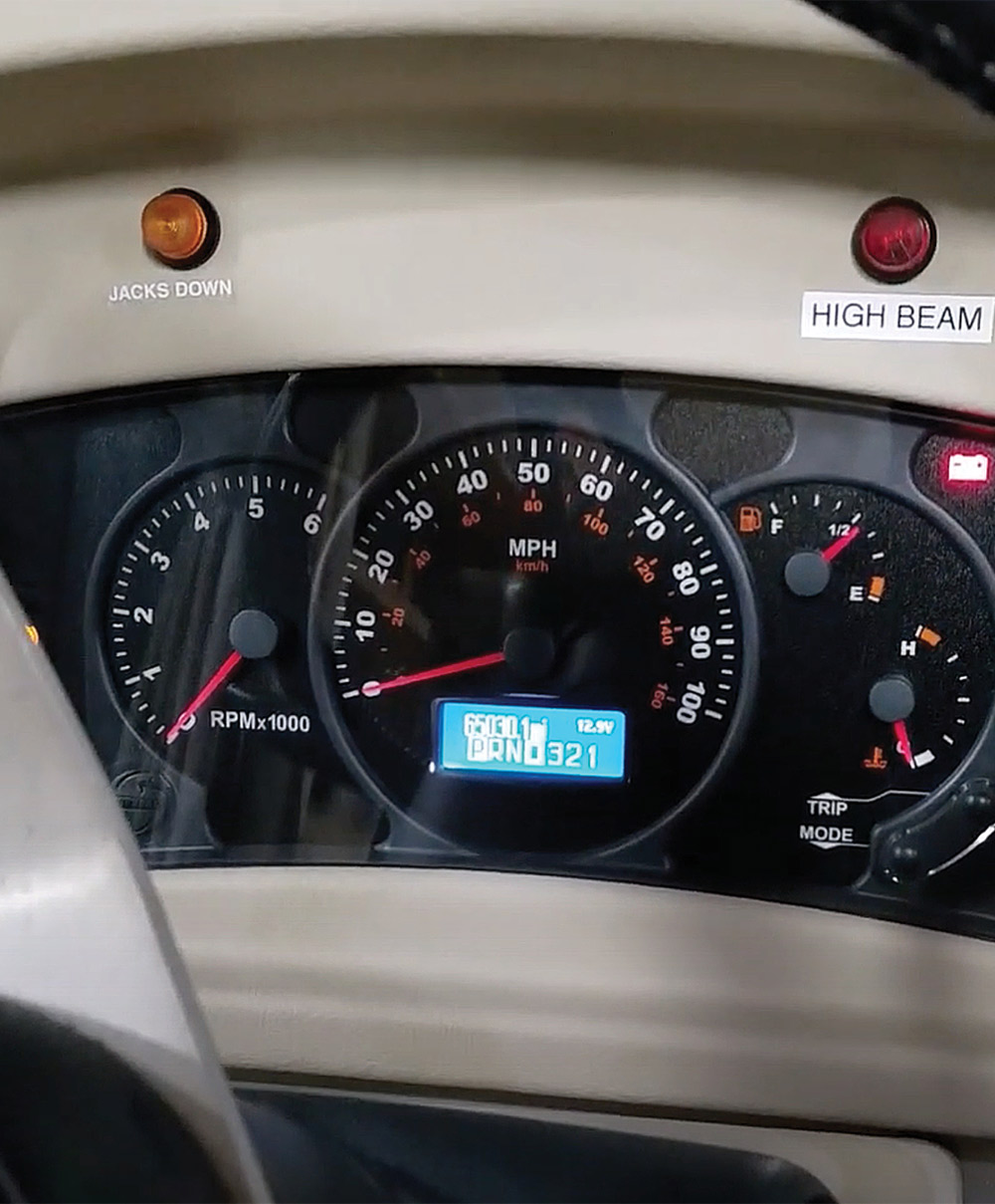
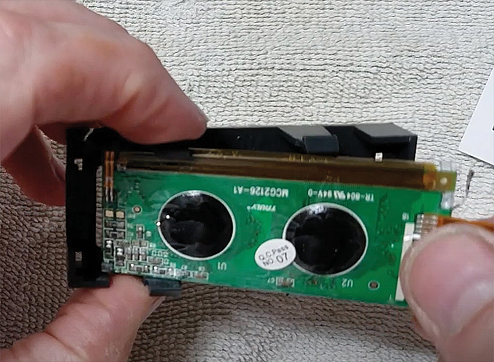
“Once delamination started, those screens would become illegible after two or three years,” he said. “We thought there has to be a better screen we can provide that doesn’t have that issue.”

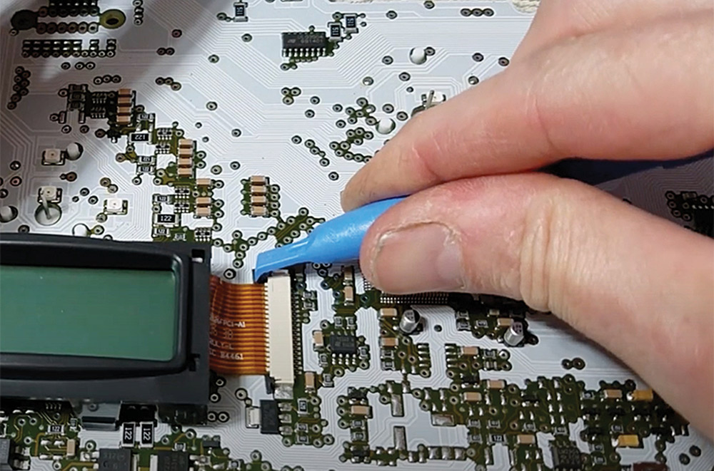
Eventually, the crew at Brazel’s RV Performance did find a suitable screen and had it custom-made to fit the Workhorse Actia instrument cluster. The company now markets the upgrade — along with a host of products for Workhorse and other chassis — at ultrarvproducts.com.

Winnebago's dash hinged upward for access to wiring and components
Since the dash in his Winnebago was hinged to allow access to the electronics behind it, Caudill used a short length of PVC pipe (notched at the top) to hold it up and out of the way. When you raise the dash, check all the wiring harnesses to ensure they aren’t being pulled too tightly — you don’t want to create unnecessary work for yourself by unplugging anything.
As Brazel stressed, this is not a replacement cluster — it’s a replacement for the errant LCD screen that’s swapped into an owner’s original instrument cluster. The replacement industrial-grade LCD screen utilizes an easily readable dark blue back-lit display for high contrast and easy daytime/nighttime reading and does not alter the vehicle mileage, which is stored on a separate memory chip on the circuit board.

The relatively inexpensive “fix” ($149.95) is available for Workhorse motorhome and commercial vehicle chassis model years 2003-2006, when the Actia-brand instrument cluster with this issue was utilized. Coincidentally, those years also were when the greatest number of Workhorse chassis were produced. If you’re unsure of fitment, RV owners can input their vehicle identification number (VIN) on the website when ordering the part and company technicians will verify parts selection by the VIN to ensure you are getting the correct component for your vehicle. It’s a great service offered by Brazel’s, which also operates workhorseparts.com and is considered the “go to” place for Workhorse parts and technical information.

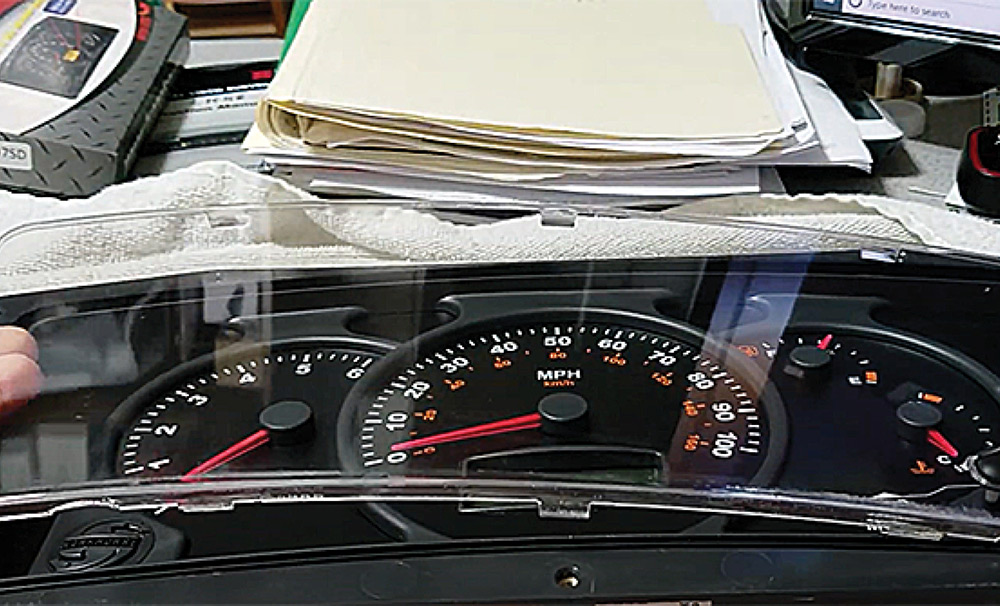
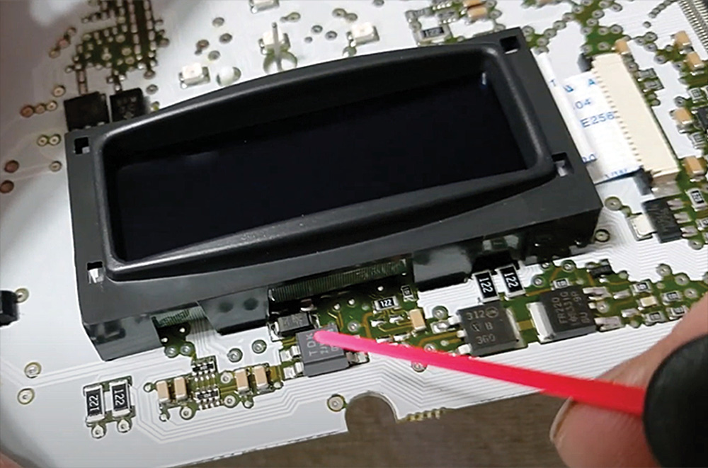
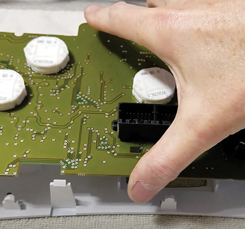
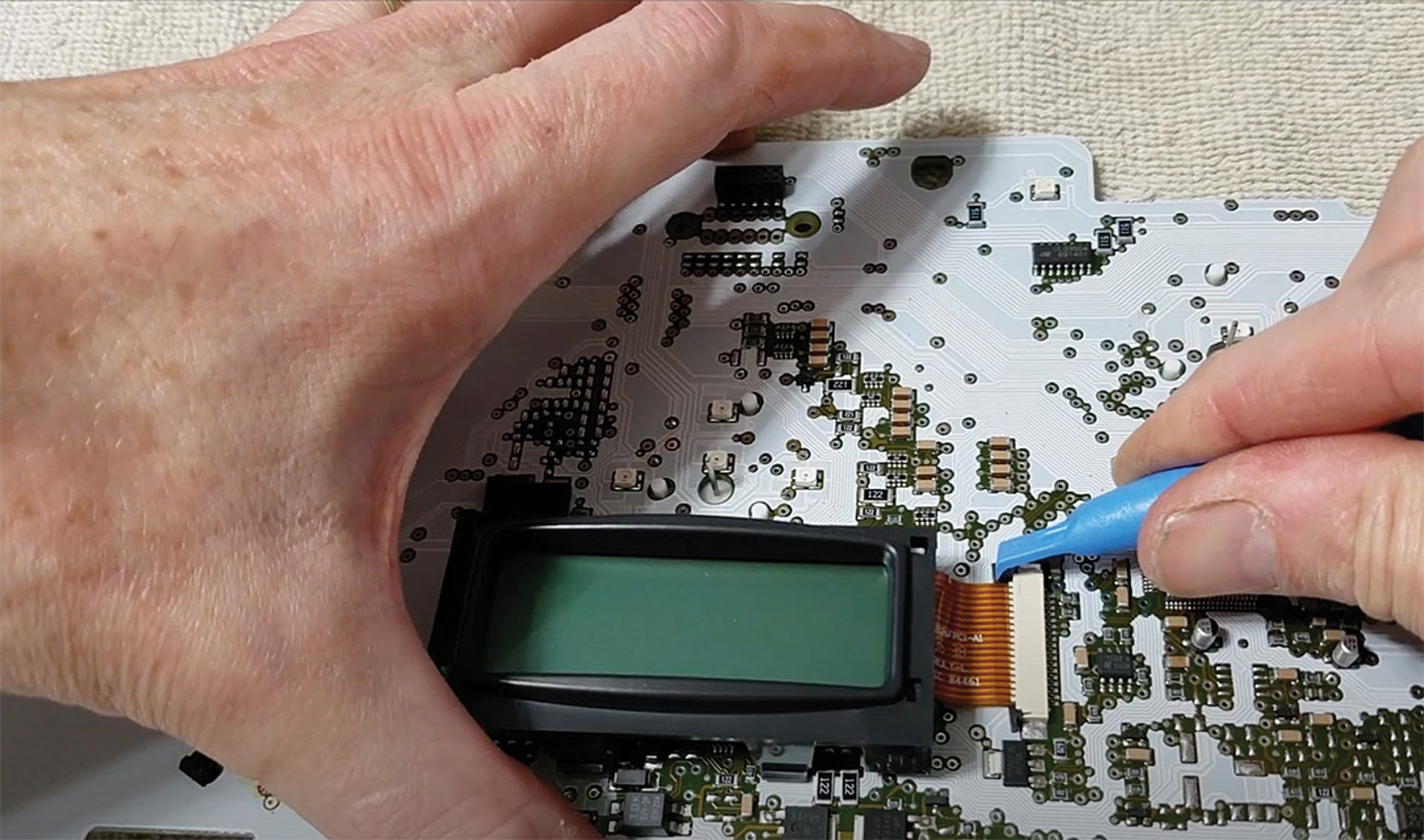
The replacement screen kit, which carries a lifetime warranty, can be replaced either by owners shipping their instrument cluster to Brazel’s or by doing it themselves — the company provides a fully illustrated installation guide with color photos detailing every step of the process. To give you an idea of the process, which only takes about 90 minutes, RV Enthusiast followed along as one owner, Kevin Caudill, swapped out the screen on his 2005 Winnebago 38J on a W-24 chassis.

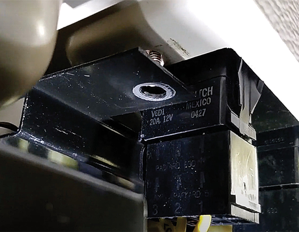
Since you are working on the motor- home’s electrical system, be sure to disconnect the engine battery before beginning to guard against inadvertently causing a short should certain connections bump against the metal frame behind the dash that’s holding everything in place.

Various plugs under dash
HWH Hydraulic Leveling panel removed
The first goal is to remove the nuts and screws holding the instrument cluster against the plastic fascia. Caudill ended up removing a few components in the way, including the dash controls for the motorhome’s HWH leveling jacks because, like most of the dash components, it screwed into the metal frame that everything else was attached to.
Removing screws from cluster faceplate
With the instrument cluster accessible, remove the Phillips head screws keeping the faceplate in place. Caudill noted that it may not be possible to find the room for a screwdriver, but inserting the Phillips head bit into a correctly sized ratchet wrench will allow you to unscrew the plate.
Rear wiring harness connections on cluster
Once unscrewed, the instrument cluster will drop out of the dash housing. Unplug the rear wiring harness connection. Getting the cluster out took Caudill about 30 minutes “and that’s with me not really knowing what I’m doing.”
Removing gauge cluster lens cover
Once the instrument cluster is free, it’s best to work on it on a soft surface such as a towel placed on a table. Remove the lens cover by pressing in and down on the clear tabs on the back of the cluster. Be very careful to not lose the Mode and Trip pins, which pull right out.
Removing gauge surround plate
Remove the gauge surround plate from the face by grabbing the surround at the 3 o’clock and 9 o’clock positions and lift straight off.
Bare gauge cluster face
Removing gauge needles
The gauge needles now need to be removed, but before you go any further, it’s recommended that you take a photo of the gauges with your smartphone to check afterward that the needles returned to the same position. There are different removal techniques: the engine tachometer and speedometer are removed by turning the needles counter-clockwise, while the temperature and fuel gauge needles are turned clockwise. Turn until each bottoms out and can be pulled off — you may find some are on pretty snug.
Separating cluster from housing
After you turn the cluster over, push in the four white tabs and push on the wiring connection plug, the cluster will separate from its housing.
Back of instrument circuit board
The circuit board for the instruments is held against the face by yet more plastic tabs. Release them by pushing on the tab as you gently lift on the board.
Unplugging LCD's ribbon wire from PCB
The screen housing also is held in place by four plastic tabs, which will have to be released. The screen housing is further attached to the circuit board by a “zero insertion force” wiring ribbon socket on one side. Carefully push the tabs out to release the ribbon from the connection, then remove the bezel.
Removing old LCD from plastic bezel
Installing new LCD into bezel
To release the old LCD screen from the plastic bezel, bend the corners of the bezel slightly to separate it. Carefully remove the protective plastic from the new screen — being careful to not touch the screen — and snap in the new screen by aligning the white ribbon with the corresponding opening in the bezel, then press it into place. You will feel (and hear) it snap into place.
Reseating LCD and bezel onto PCB
Line up the ribbon with the socket and carefully slide it into place; when installed correctly, you will no longer see the contact points on the ribbon. Lock the plastic tabs into place (you’ll need to carefully press them in at the same time). When reattaching the bezel to the circuit board, be careful not to damage other components on the circuit board, particularly those directly under the bezel.
Placing circuit board back into plastic housing
At this point, the screen installation is done; now everything simply needs to be reassembled. Start by laying the fascia face-down on the towel and pressing the circuit board back into its holder, then install the board into the case. Caudill used a microfiber towel to guard against getting fingerprints on the face.
Gauge needles reinstalled
Reinstall the gauge needles — which, Caudill noted, “go in a lot easier than they came out.” Make sure you don’t feel any drag on them when turning; Brazel’s recommends keeping a fingernail’s width of space between the cap and the face so it won’t drag on it.
New LCD working and displaying various technical information screens
Before reinstalling the completed instrument cluster into the dash, it needs to be checked to ensure the gauges are working correctly. Reattach the battery connections, then turn on the ignition without starting the engine. Press and hold the “mode” button for 20 second, then release. The LCD display will yield a number of options, from adjusting the screen contrast and restoring default settings to engine hours and max vehicle and engine speeds. Scroll to “cluster diagnostics,” then “gauge test” and it will automatically test each gauge for correct operation at 0%, 50% and 100%. If everything lines up correctly, disconnect the battery again and reinstall the instrument cluster, taking pains to ensure you don’t accidentally pinch any wires when you lower the dash back into place.