


Power Up
[maghub_sidebar]
Power Up title
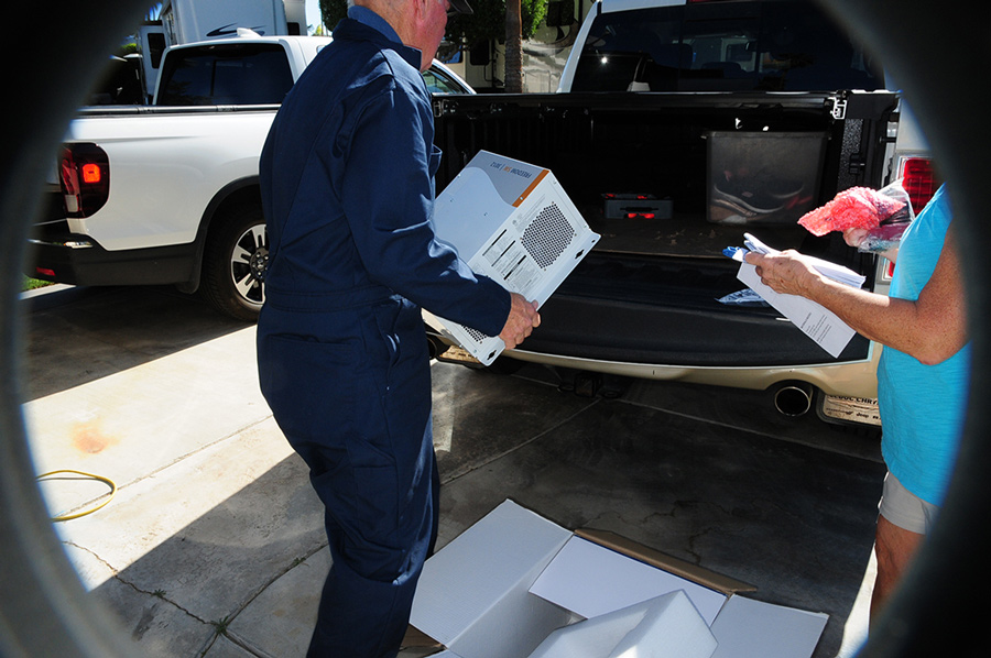
view through a peephole of a man loading Freedom SW 3012 into the back of a truck
Power Up title
view through a peephole of a man loading Freedom SW 3012 into the back of a truck
When the inverter/charger goes kaput, Xantrex has a solution for just about any configuration. The Freedom SW 3012 was a perfect retrofit for the old inverter in this motorhome.
By Bob Livingston / Photos by the author
Y

ears ago, having a inverter capable of providing maybe 150 watts of modified sine wave power was almost a novelty. I remember my first 100-watt inverter. It was packed inside a bulky aluminum housing and powered a small black and white TV (also a bit of a novelty for those of us who turned to RVing as an outlet for leaving our daily routines behind). Today, inverters are becoming standard equipment on many RVs — and combined with a powerful, smart battery charging circuit, are becoming indispensable, especially for those RVs equipped with residential refrigerators.

In fact, sophisticated inverter/chargers capable of conditioning lithium batteries and part of high-tech packages that run just about everything in an RV — sans an umbilical cord — are all the rage these days for those who relish boondocking. Many larger systems can even run air-conditioners, eliminating the need for noisy generators. The more elaborate systems will have a large 3,000-watt pure sine inverter, a big bank of lithium batteries and a significant array of solar panels.

But while most of the inverters on the market have decent lifespans, higher dependency on off-grid power can lead to inopportune inverter malfunctions — which can pretty much render the 120-volt AC electrical system kaput when camping without hookups and/or running the generator all the time. That’s exactly what happened to the owners of this 40-foot diesel pusher motorhome. And, as expected, it happened during an inopportune time: while on their way to their winter destination.

Ordering an exact replacement for their 2,800-watt inverter proved futile as the suppliers got caught up in the supply chain dilemma. Fortunately, Xantrex, a name synonymous with battery charging and inverter technology, had a more products in the pipeline at the time, allowing a Freedom SW 3012 3,000-watt inverter (xantrex.com) to be retrofitted in a more timely manner.

Xantex prides itself in being RV power solutions company. The Canadian-based entity offers inverter/chargers, control panels, solar systems, lithium batteries and a bunch of other accessories that make swapping equipment relatively easy — and just about everything the company makes benefits from advanced technology. For this project, the Freedom SW 3012 made the most sense, since the motorhome was wired with dual outputs through two breakers. This inverter/charger requires two 120-volt AC inputs, typically arranged in a 120/240-volt AC configuration to distribute the load on both sides of a 50-amp RV service provided by RV site hookups (which is also 120/240 volts AC). In the motorhome, these inputs were protected by 30-amp breakers labeled “Charger 1” and “Charger 2.” The 10-gauge wires from these breakers were routed into the inverter cabinet and were readily identifiable with a multimeter; the neutrals were grounded.
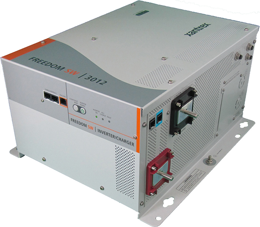
second-generation Xantrex Freedom SW
The second-generation Xantrex Freedom SW inverter/chargers feature improved AC transfer/AC input detection time, providing the ability to transfer AC loads to batteries in less than 10 milliseconds when incoming grid or generator lower is lost.
The inverter/charger we replaced had two cables supplying the AC input power, so we connected the black wires from each to the L1 and L2 positions on the Xantrex inverter/charger, respectively. Since we were working with two cables, the neutrals were terminated on the single lug and the grounds were connected to the ground bus. These wires must connect only to the input side of the inverter/charger (not the output) or severe damage could result. When complete, the voltage on each of L1 and L2 measured 120 volts AC to ground with 240 volts AC between them.

The output terminals of the Xantrex inverter/charger are labeled L1 and N1, and L2 and N2, respectively. They connect to a sub-panel with an un-grounded neutral bar. In the case of this motorhome, the sub-panel is an integral but isolated part of the main AC panel. The inverter output breakers are labeled “Inverter 1” and “Inverter 2.” The output of the inverter connects to each of the breakers, respectively; the neutrals are both connected to the sub-panel neutral bar and the grounds are connected to the chassis ground. Power to the sub-panel is either supplied directly by the inverter or by flow-through from shore power or the generator.
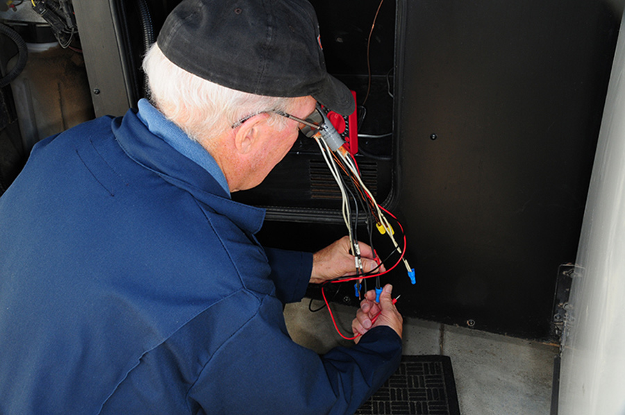
man working on wiring
Once the original inverter/charger was removed, the wiring was identified and marked to facilitate the new install. The compartment was also cleaned thoroughly.
Wiring mistakes can be costly, often resulting in a blown-up inverter. If you are not comfortable with 120-volt AC wiring, leave this part of the job to an electrician. However, most “weekend wrenchers” can do the bulk of the work installing the inverter, which is straightforward but time-consuming.

The first step was making sure the incoming power was disconnected from all sources, the breakers closed and the cables from the battery bank removed. As each wire was removed from the existing inverter, the ends were identified and marked. Once the original inverter was free from the cables and wires, it was unbolted and removed and the compartment cleaned thoroughly. These inverters are heavy, so enlist some help if needed.

In order to simplify the process, we surveyed the install strategy and did as much as we could on the tailgate of the pickup that was towed behind the motorhome. We decided to use ¾-inch nylon liquid-tight Type B fittings for routing the wiring through the knockouts in the side of the inverter. It was a good idea at the time, but in the end we were not able to route the wiring without removing these fittings and pulling with a needle-nose pliers. And, working space to tighten the flat nuts was very tight, requiring a few choice words to get these fittings removed and reinstalled, but we got there.
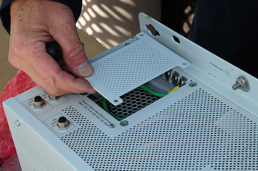
access panel was removed, exposing positions for hooking up the wiring
The access panel was removed, exposing positions for hooking up the wiring. There’s not a ton of room in there, but with patience the installer can get the job done.
The inverter was then test mounted in the compartment, which fit like a glove, and the holes for the front brackets were drilled to drive in the appropriate lag bolts to keep the housing from moving. A paper template was provided, which can be cut out and laid on the compartment floor for locating the back bolts. If you don’t predrill and fit the bolts in place after temporarily removing the inverter, the task is pretty much not possible.

Before mounting the inverter permanently, the wiring for the battery temperature sensor had to be run, which turned out to be the hardest part of the job. We first removed the old sensor and cut and pulled most of the cable for discarding. Routing the new cable requires some engine compartment calisthenics (and, admittedly, more choice language). Fortunately, we were able to grab just enough of the old cable to attach the end of the new one and fish it through the back wall in the inverter compartment. Any loose wire was cable-tied in place, being careful to route around any obstructions and hot zones.

using scissors to cut the paper template
A paper template is provided with the kit, which will make it possible to locate holes for hold-down bolts.
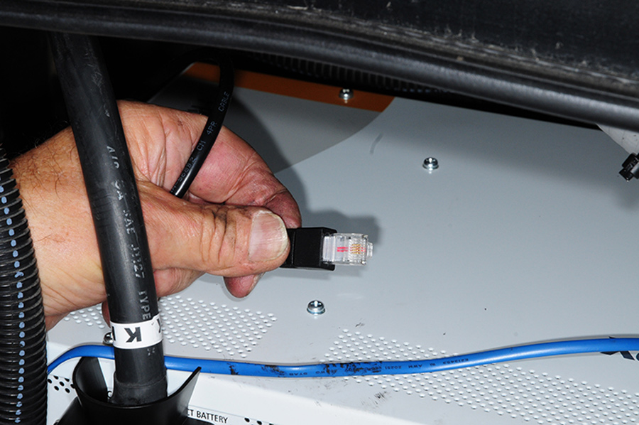
The wiring identifications were again verified using a multimeter and connected to the inverter. A network cable adapter pigtail from Xantrex (Part. No. 808-9010) allowed us to connect to the remote panel, a network terminator was plugged in to the unused port, battery cables were attached (with protective boots) and we were done inside the inverter compartment. If you do your homework and identify the wiring in advance, figure on around two hours to complete this part of the installation.

Before moving to the cockpit of the motorhome to install the remote panel, we tested the wiring again, flipped the breakers and confirmed that the output was indeed working as designed and checked for charging current.

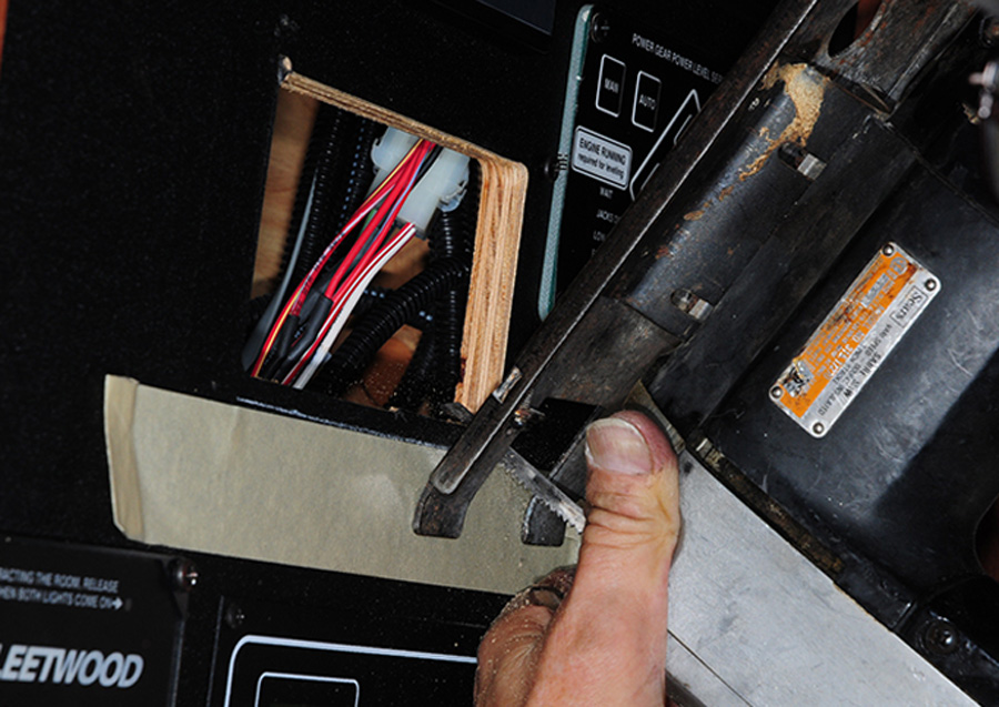
The original inverter/charger’s remote panel was removed in order to pull the cable needed to hook up the new Xantrex panel. After marking the cutting zone with another Xantrex-supplied template, a hole was made in the wood panel inside the access compartment above the passenger seat. We used a jig saw, but an oscillating tool could have also been called into service here. The network cable adapter pigtail from Xantrex made short work of connecting the new remote panel — no muss, no fuss, no wire crimping and no guesswork.

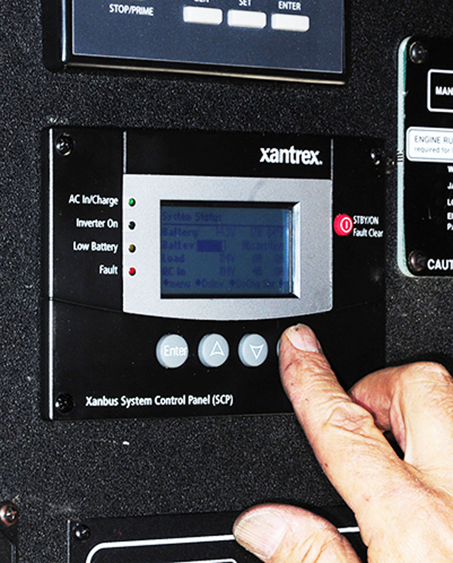
Xantrex’s System Control Panel (remote) allows the user to monitor function as well as make parameter changes, which is important, for example, when connecting the inverter/charger to lithium batteries. The substantial instruction booklet guides the user through the steps and provides great insight for monitoring and understanding the various functions.
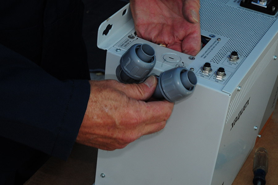
¾-inch nylon liquid tight Type B fittings
We elected to use ¾-inch nylon liquid tight Type B fittings for routing the wiring into the inverter/charger. Installing them before moving the inverter/charger into the motorhome compartment proved to be premature since the wires needed extra prodding for routing.
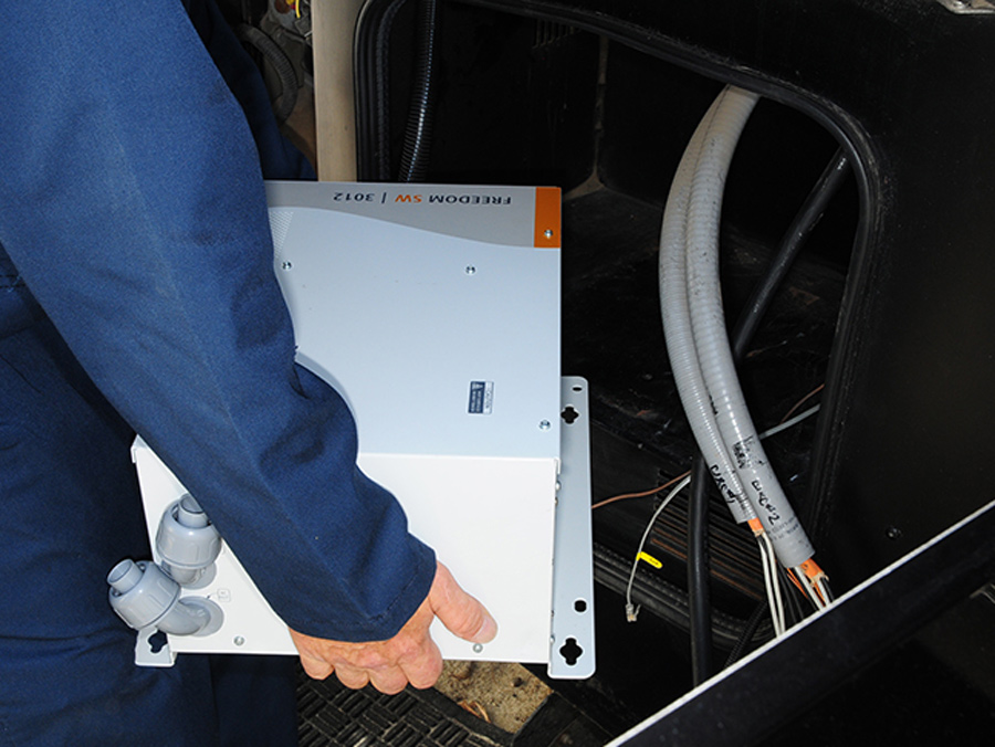
prep work done of the tailgate of the pickup dinghy
Our prep work was done of the tailgate of the pickup dinghy. It takes some muscle to move the inverter/charger into the compartment, but it fit like a glove.
The Freedom SW 3012 inverter/charger employs hybrid technology capability that combines with hookup and generator power to handle higher loads. For example, if you are hooked up to 30-amp power and the load requirement hits 40 amps, the inverter will automatically kick in the additional current to run the appliance(s). When the load decreases, the circuit will charge the batteries while 120-volt AC power is available.

This unit offers state-of-the art pure sine wave power, so sensitive electronics will be safe, and longer surge times allow operation of motor loads and other high current items like hot plates and coffee pots. Three-stage smart charging is supported by a 100-amp rating. Retail price of the Freedom SW 3012 is $2,698; the System Control Panel has a $314 price tag and the Telephone to CATS cable adapter pigtails are $39 for two.

Living in an RV without an inverter these days is like driving without wheels. Making 120-volt AC power from a battery bank brings off-grid living to a level where compromising is no longer necessary. Harness the sun to keep batteries conditioned and tie them into an inverter, and RVers can enjoy boondocking like never before.
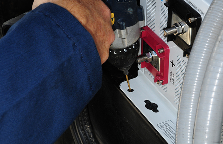
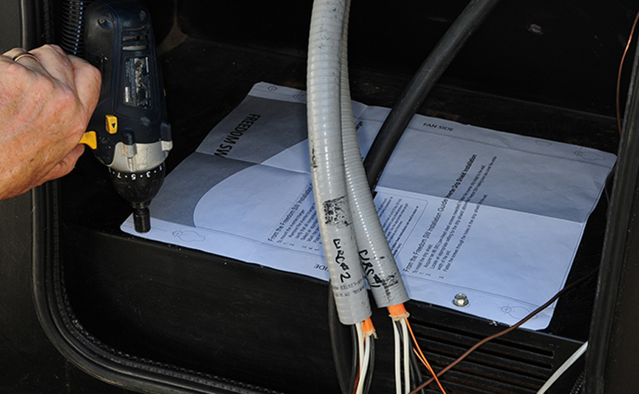
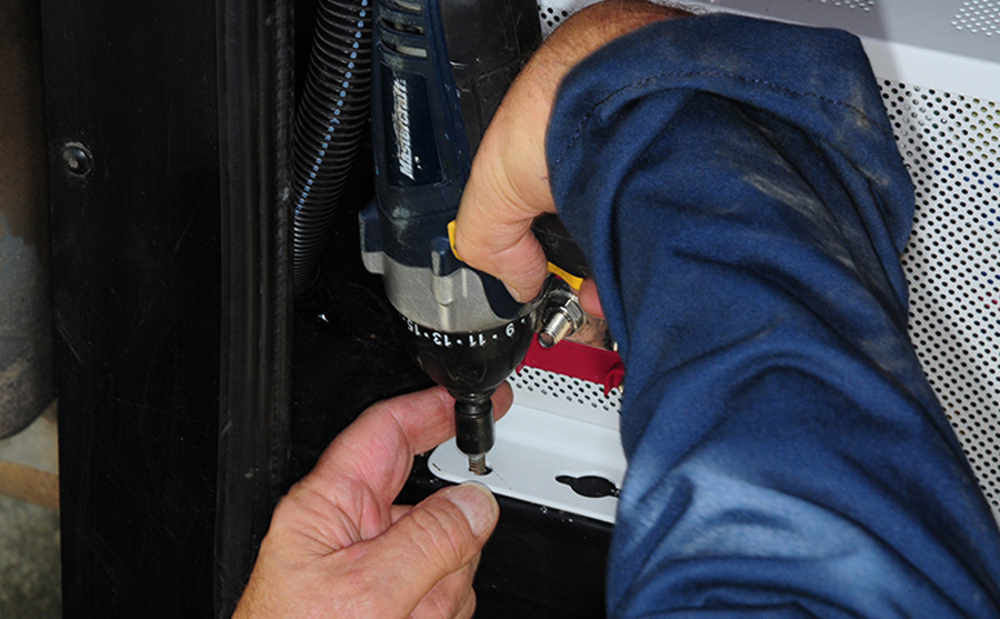
Pilot holes were drilled through the openings in the front flange
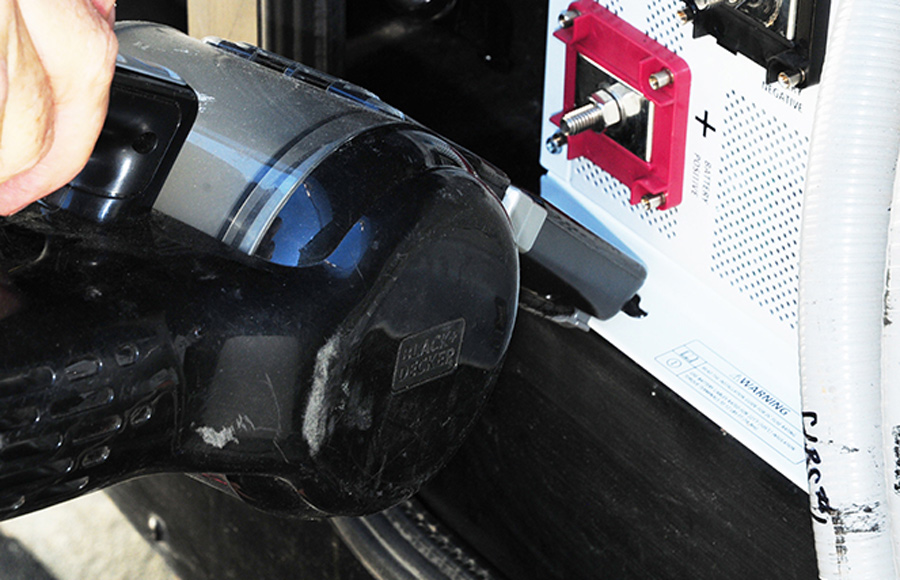
shavings were removed with a handheld vacuum cleaner after each hole was drilled
Pilot holes were drilled through the openings in the front flange. There was just enough room to use a small drill motor. Metal shavings can be death to any electrical component. Here the shavings were removed with a handheld vacuum cleaner after each hole was drilled.
tighten the lag bolts through the marked positions in the paper
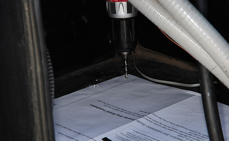
rear holes being drilled through the template
While it’s possible to tape the template into position, a more positive approach is to tighten the lag bolts through the marked positions in the paper, which made finding the rear locations more accurate. The rear holes were then drilled through the template.
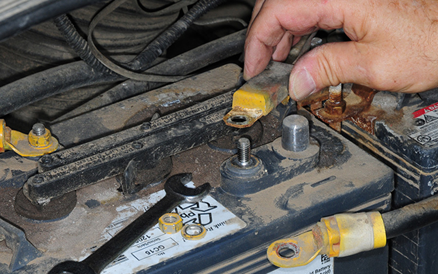
old temperature sensor being removed from one of the batterie
new temperature sensor that came with the inverter/charger being installed
The old temperature sensor was removed from one of the batteries and the new one that came with the inverter/charger was installed in its place. Loose wires were then cable-tied out of the way.
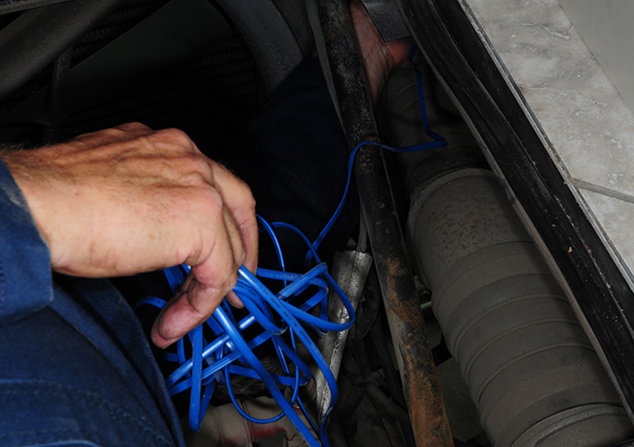
routing the cable from the new battery temperature sensor into the compartment
The hardest — and most time consuming — part of this particular installation was routing the cable from the new battery temperature sensor into the compartment. There’s plenty of cable provided, but at times it felt like working with a handful of spaghetti.
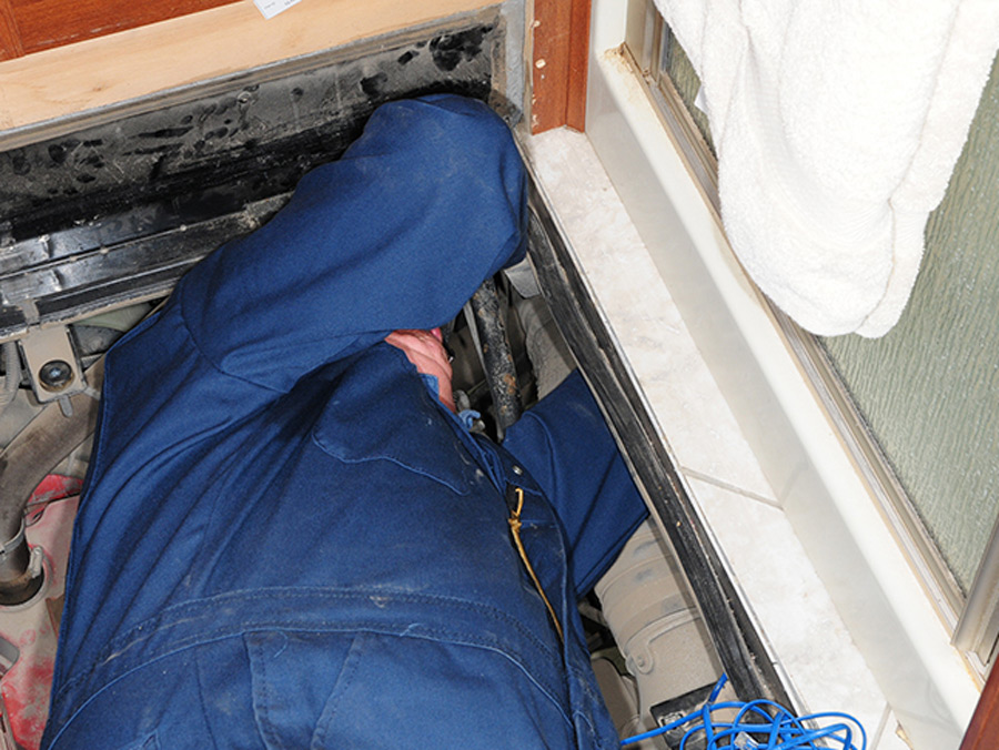
Access to the engine compartment was via the trap door in the rear bathroom
Access to the engine compartment was via the trap door in the rear bathroom; decorative paneling was removed to make way for the door. You’ll likely have to lay down on the job here to route the sensor cable.
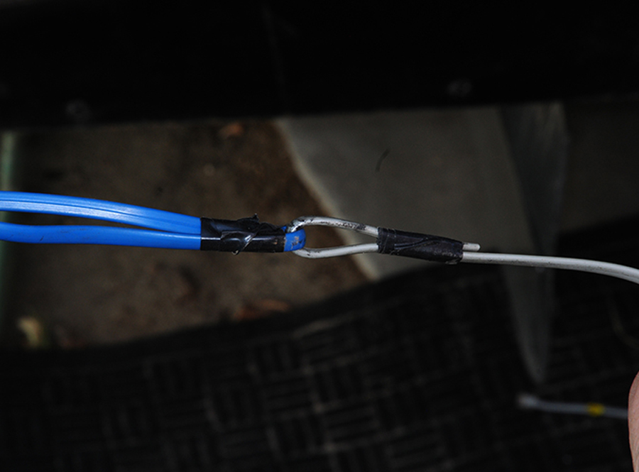
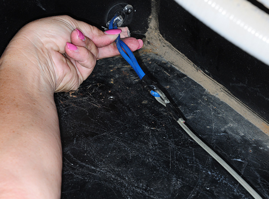
Most of the old sensor cable was cut away, but one end was used as a fish wire to find a suitable pathway to the compartment where the inverter/charger is mounted
cable was pulled through without any damage to the insulation
Most of the old sensor cable was cut away, but one end was used as a fish wire to find a suitable pathway to the compartment where the inverter/charger is mounted. Fortunately, the cable was pulled through without any damage to the insulation.
install the rear flange bolts to the compartment floor
The last step before mounting the inverter/charger was to install the rear flange bolts to the compartment floor. There’s almost no room to work once the inverter/charger is in place, so slots in the flange made it possible to locate and tighten the bolts by feel only. The front flange bolts were then tightened, and the inverter/charger housing was solid as a rock
bare ground wire was attached the appropriate lug on the mounting flange
The bare ground wire was attached the appropriate lug on the mounting flange.
remove the fittings that were previously installed into the inverter/charger housin
We had to remove the fittings that were previously installed into the inverter/charger housing in order to push the wires through the bend. This proved to be difficult on two fronts: The fittings were a bear to remove since there is little working space, and the wires did not want to cooperate until a needle-nose pliers was called in to help.
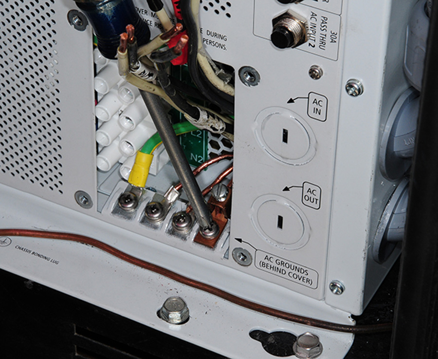
Terminals were crimped to the ground wires and attached to the bus in the bottom of the wiring access area
Terminals were crimped to the ground wires and attached to the bus in the bottom of the wiring access area.
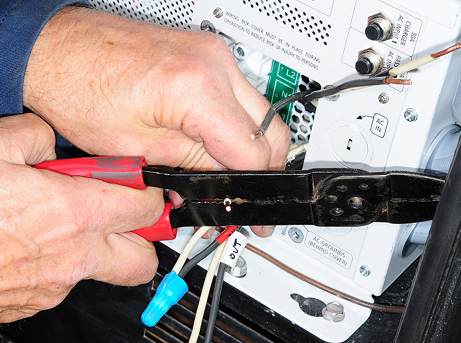
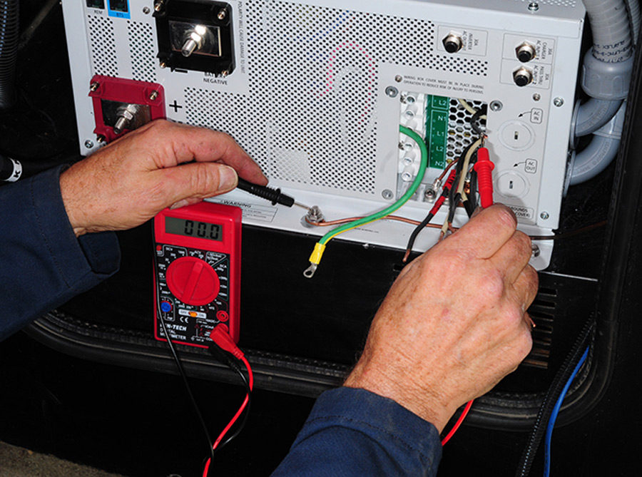
ends of all the wires were cut and stripped to fit precisely into the appropriate terminals in the inverter/charger
wires were again tested to make sure they were identified and marked correctly
The ends of all the wires were cut and stripped to fit precisely into the appropriate terminals in the inverter/charger. This is an area where neatness pays off. Just to be safe, the wires were again tested to make sure they were identified and marked correctly. Failure to wire the inverter/charger properly can result in catastrophic damage.
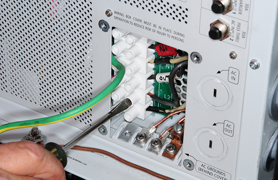
AC input and output terminals are clearly marked inside the access panel
AC input and output terminals are clearly marked inside the access panel, and the instruction booklet provides detailed instructions on the wiring set-up, which must be followed precisely to prevent damaging the inverter/charger. Seek professional help if you are not comfortable with AC wiring.
Xantrex offers conversion pigtails that adapt the ends of the original cable to those needed to connect the inverter/charger and proprietary remote
Rather than re-routing a new phone-type cable to the cockpit for connection into the new remote panel, Xantrex offers conversion pigtails that adapt the ends of the original cable to those needed to connect the inverter/charger and proprietary remote. This was a tremendous time saver.
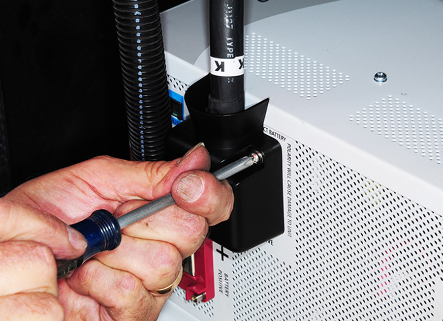
Battery cables were connected to the clearly marked and color-coded studs on the inverter/charger
protective covers were then installed to complete this part of the process
Battery cables were connected to the clearly marked and color-coded studs on the inverter/charger. The protective covers were then installed to complete this part of the process.
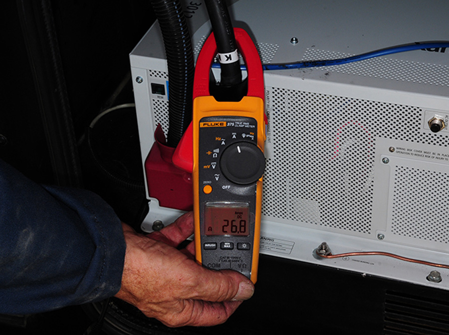
inverter/charger was turned on and battery charging was checked with a clamp-on amp meter
Once the wiring was confirmed, the inverter/charger was turned on and battery charging was checked with a clamp-on amp meter. The Freedom SW 3012 provides three-stage smart charging and can be set for lithium batteries; the project coach was fitted with flooded cell batteries.
old remote panel was unplugged and returned to the original mounting location
The old remote panel was unplugged and returned to the original mounting location rather than building a plate to cover up the hole.
provided paper template was used to locate the new, larger remote control/monitor into the wood backing
jig saw was a little big for cutting the hole, but it worked
A provided paper template was used to locate the new, larger remote control/monitor into the wood backing in the access compartment above the passenger seat in the cockpit. A jig saw was a little big for cutting the hole, but it worked. A better solution is to use an oscillating tool.
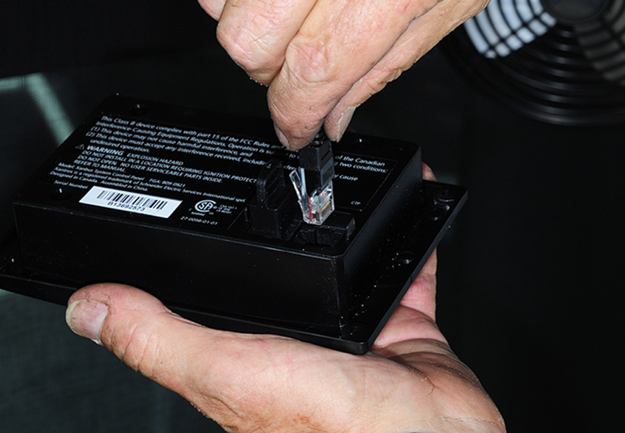
second pigtail to convert the old phone-type connector
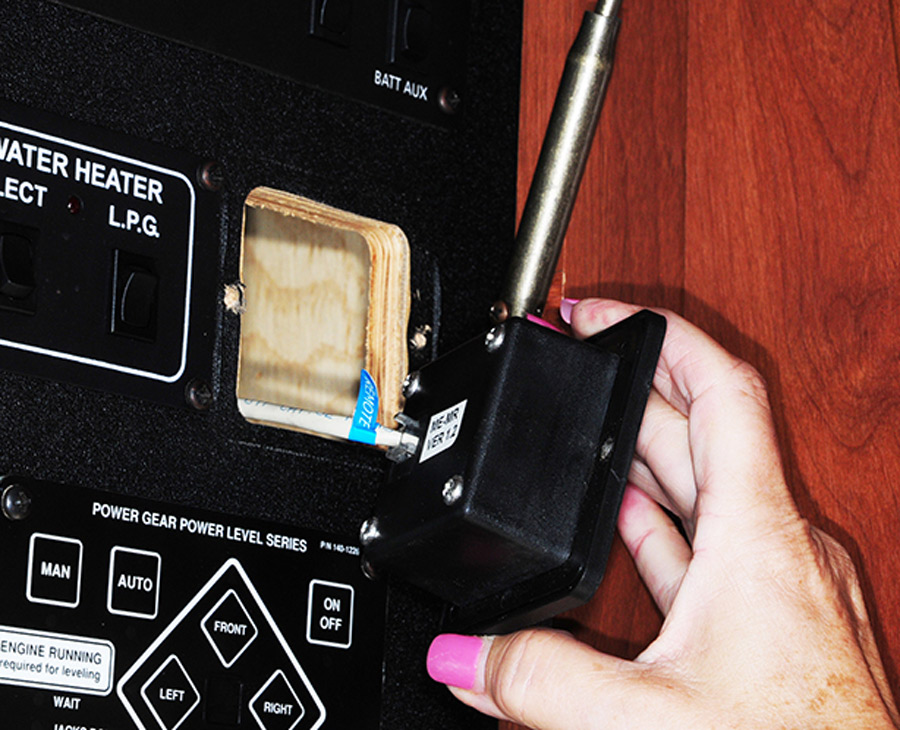
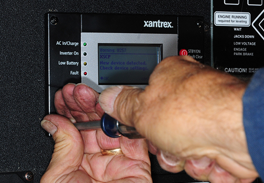
provided screws were used to secure the panel into the wood backing inside the access compartment
A second pigtail to convert the old phone-type connector again made it easy to hook up the Xantrex remote control/monitor. The provided screws were used to secure the panel into the wood backing inside the access compartment.
Xantrex Systems Control Panel
The Xantrex Systems Control Panel is a powerful tool, which allows the owner to set battery type and a host of other parameters for keeping abreast of system operations. A well-written instruction booklet guides the user through the process.